
A variable-angle two-dimensional ultrasonic vibration assisted machining platform based on flexible hinges

A two-dimensional ultrasonic vibration and flexible hinge technology, applied in the direction of fluid using vibration, can solve problems such as difficulty, high cost of transformation, and complicated design and development process, and achieve the effects of avoiding transformation, high precision and efficiency

Active Publication Date: 2020-05-05
NORTHEASTERN UNIV LIAONING
View PDF4 Cites 0 Cited by
  • Summary
  • Abstract
  • Description
  • Claims
  • Application Information

AI Technical Summary

Problems solved by technology

Limited to ultrasonic vibration-assisted milling, most of the processing is realized by modifying the spindle, which is expensive and difficult to modify. At the same time, the ultrasonic vibration method of the modified spindle can only drive smaller tools or grinding heads, which is very difficult in actual processing. It is difficult to meet the processing requirements, so it is a feasible idea from the perspective of workpiece vibration
On the other hand, the study of one-dimensional ultrasonic vibration has made great progress, and two-dimensional and even three-dimensional ultrasonic vibration has become a research hotspot. If the two-dimensional vibration is realized by transforming the main shaft, only longitudinal-bending compound vibration or longitudinal-torsional compound vibration can be used. , its design and development process is very complicated, and can only achieve two-dimensional vibration at a fixed angle

Method used


Image

  • A variable-angle two-dimensional ultrasonic vibration assisted machining platform based on flexible hinges
  • A variable-angle two-dimensional ultrasonic vibration assisted machining platform based on flexible hinges
  • A variable-angle two-dimensional ultrasonic vibration assisted machining platform based on flexible hinges

Examples


Embodiment Construction

[0022] The present invention will be further described in detail below in conjunction with the accompanying drawings and embodiments.

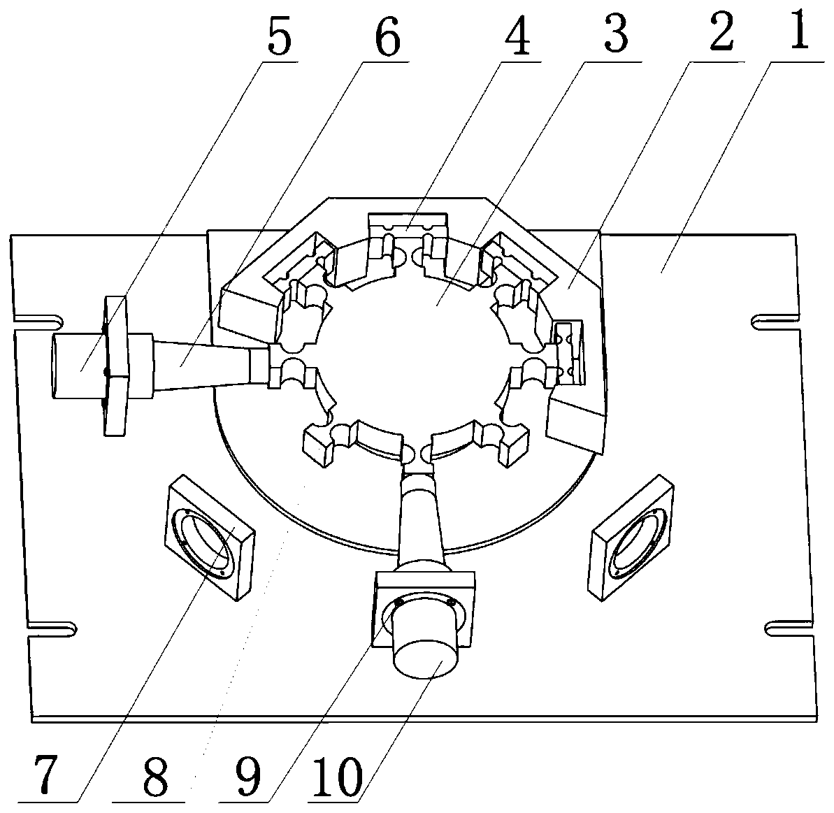
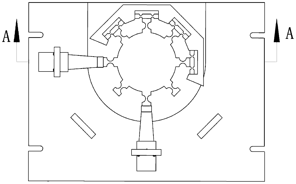
[0023] Such as Figure 1 to Figure 4 As shown, a variable-angle two-dimensional ultrasonic vibration auxiliary processing platform based on flexible hinges includes a rectangular bottom plate 1 and a vibrating block 3. The bottom plate 1 cooperates with the seat ring of the thrust bearing 11 through an annular platform provided on its upper surface. The vibrating block 3 cooperates with the shaft ring of the thrust bearing 11 through the circular boss provided on its lower surface, so as to realize the Z-direction support for the vibrating block 3, and at the same time, because the reasoning bearing does not limit the axial displacement, it can realize two-dimensional Ultrasonic vibration, the upper surface of the bottom plate 1 is provided with four flange seats 7 along the circumference, and the first ultrasonic vibrator 5 and the second ult...


PUM


Abstract

A variable-angle two-dimensional ultrasonic vibration-assisted processing platform based on a flexible hinge, including a base plate and a vibration block. The base plate cooperates with the seat ring of the thrust bearing through an annular platform provided on its upper surface, and the vibration block is provided through its lower surface. The circular boss cooperates with the shaft ring of the thrust bearing. The upper surface of the base plate is provided with several flange seats along the circumferential direction. The first ultrasonic vibrator and the second ultrasonic vibrator are respectively installed on two of the flange seats. The horns on the first ultrasonic vibrator and the second ultrasonic vibrator are in close contact with the vibrating block respectively. A mounting base is provided on the upper surface of the base plate. A first flexible hinge is installed in the U-shaped groove of the mounting base. The first flexible hinge is connected to the vibrating block. The vibrating mass fits snugly. The first ultrasonic vibrator and the second ultrasonic vibrator realize two-dimensional ultrasonic vibration processing of the workpiece, avoiding the modification of the spindle. A thrust bearing is installed between the base plate and the vibration block to support the vibration block in the Z direction without affecting the vibration of the vibration block in the XY plane.

Description

technical field [0001] The invention belongs to the technical field of ultrasonic processing, and in particular relates to a variable-angle two-dimensional ultrasonic vibration auxiliary processing platform based on a flexible hinge. Background technique [0002] Since the 1950s, ultrasonic vibration-assisted machining has been gradually applied in the industrial field, and has attracted great attention and interest from many scholars. Ultrasonic-assisted machining technology has developed rapidly. In recent years, it can be seen that ultrasonic-assisted processing technology accounts for a large proportion in the processing technologies of brittle and hard materials represented by engineering ceramics and difficult-to-machine materials represented by titanium alloys. Compared with traditional machining, ultrasonic vibration assisted machining technology has been proved to have clear advantages in reducing cutting force, reducing cutting heat, improving machined surface qual...

Claims


Application Information

Patent Timeline
Patent Type & Authority Patents(China)
IPC IPC(8): B06B1/06
CPCB06B1/0622
Inventor 李宗元朱立达杨志超
Owner NORTHEASTERN UNIV LIAONING
Learn More