Retinal blood vessel syringe for ophthalmologic operation robot
A retinal vascular and ophthalmic surgery technology, applied in ophthalmic surgery and other directions, can solve the problems of low operation and positioning efficiency, limited needle tip movement, etc., to achieve the effect of improving efficiency, avoiding assembly errors and accurate positioning
- Summary
- Abstract
- Description
- Claims
- Application Information
AI Technical Summary
Problems solved by technology
Method used
Image
Examples
specific Embodiment approach 1
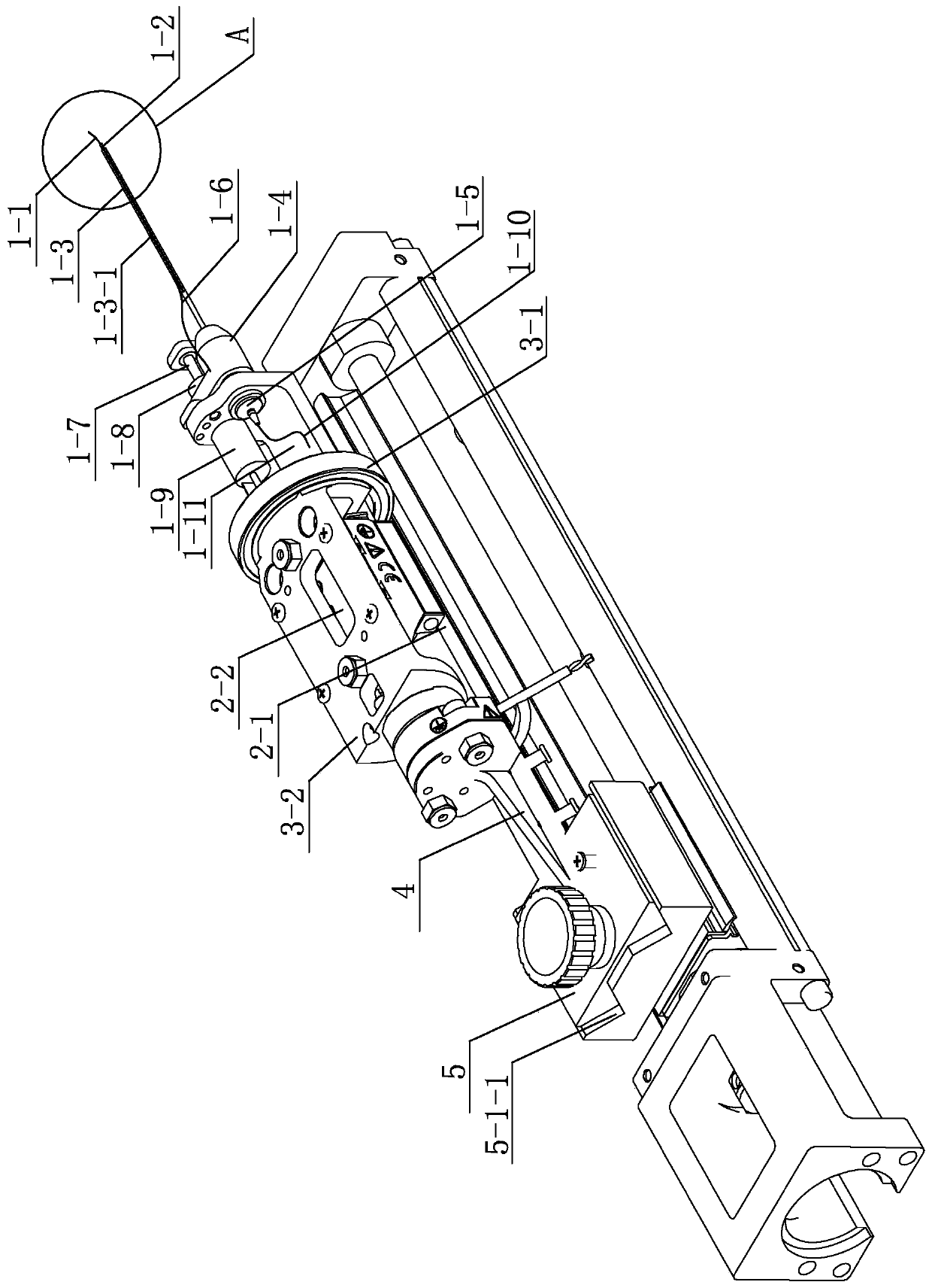
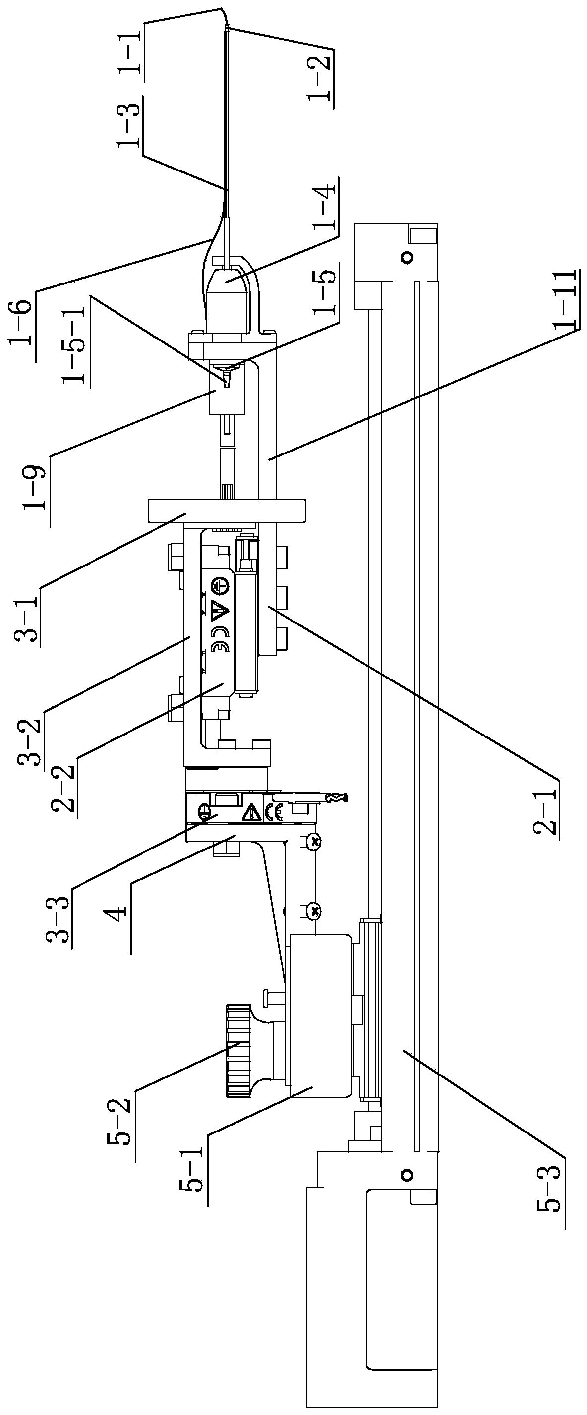
[0017] Specific implementation mode one: combine Figure 1 to Figure 5 Describe this embodiment, a retinal blood vessel drug injector for an ophthalmic surgery robot in this embodiment includes an actuator fixing base 4, which also includes a needle tube group module 1, a feed module 2 and a rotation module 3, and the needle tube group module 1 Installed on the feed module 2 and driven by the feed module 2, the feed module 2 is installed on the front of the rotation module 3, and the needle tube group module 1 and the feed module 2 are driven by the rotation module 3. Rotation, the rotation module 3 is installed on the actuator fixing seat 4; the needle tube set module 1 includes a needle tip 1-1, an inner tube 1-2, an outer tube 1-3, an outer tube connector 1-4, an inner tube connector 1- 5. Bragg fiber grating 1-6, lead screw 1-7, lead screw nut 1-8, stepper motor 1-9, injection hose 1-10 and installation frame 1-11, the installation frame 1-11 is installed in the For the f...
specific Embodiment approach 2
[0021] Specific implementation mode two: combination Figure 1 to Figure 3 and Figure 5 The present embodiment will be described. The tip 1-1 of this embodiment has an upward bend of 45° at its end, and the diameter of the needle tip 1-1 is 0.4 mm. Such setting facilitates accurate oblique insertion into blood vessels during operation. Other compositions and connections are the same as in the first embodiment.
[0022] When the needle of this embodiment is inserted into the blood vessel, it generally needs to be inserted at a certain angle. If it is inserted vertically into the blood vessel, it is very easy to puncture the whole blood vessel. Experiments have proved that the best inclination angle is generally 25-35 degrees. For this purpose, the needle tip designed in this project has a 45-degree angle bend, which is matched with the angle difference between the inner and outer tubes and the blood vessel, so that the angle between the needle tip and the blood vessel during...
specific Embodiment approach 3
[0023] Specific implementation mode three: combination Figure 1 to Figure 3 Describe this embodiment, the feed module 2 of this embodiment includes a feed connector 2-1 and a direct-motion inertia piezoelectric motor 2-2, the feed connector 2-1 is connected to the mounting frame 1-11, and the direct-motion inertia The piezoelectric motor 2-2 is installed on the feeding connector 2-1 and drives the needle tube group module 1 to complete the linear feeding action. In this way, the direct-motion inertial piezoelectric motor 2-2 is connected to the feed connector 2-1 through bolts. The feed connector is connected with the needle tube set module 1 at the same time, so as to achieve the purpose of pushing the entire needle tube set to complete the linear feed motion through the inertial piezoelectric motor 2-2. Other compositions and connections are the same as those in Embodiment 1 or Embodiment 2.
[0024] The upper end surface of the feed connector 2-1 in this embodiment is pr...
PUM
 Abstract
Description
Claims
Application Information
 - R&D
- Intellectual Property
- Life Sciences
- Materials
- Tech Scout
- Unparalleled Data Quality
- Higher Quality Content
- 60% Fewer Hallucinations
Browse by: Latest US Patents, China's latest patents, Technical Efficacy Thesaurus, Application Domain, Technology Topic, Popular Technical Reports.
© 2025 PatSnap. All rights reserved.Legal|Privacy policy|Modern Slavery Act Transparency Statement|Sitemap|About US| Contact US: help@patsnap.com


