
Electronic module

A technology of electronic modules and power terminals, applied in electronic switches, circuits, electrical components, etc., can solve the problems of increasing switching noise and surge voltage, shortening the life of half-bridge switches, increasing heat generation, etc. Effects of Noise and Surge Voltage

Active Publication Date: 2019-10-22
SHINDENGEN ELECTRIC MFG CO LTD
View PDF10 Cites 0 Cited by
  • Summary
  • Abstract
  • Description
  • Claims
  • Application Information

AI Technical Summary

Problems solved by technology

[0007] In the phase where the current path is longer, switching noise and surge voltage will increase, resulting in increased heat generation
thus shortening the switching life of the half-bridge

Method used


Image

  • Electronic module
  • Electronic module
  • Electronic module

Examples


Embodiment 1

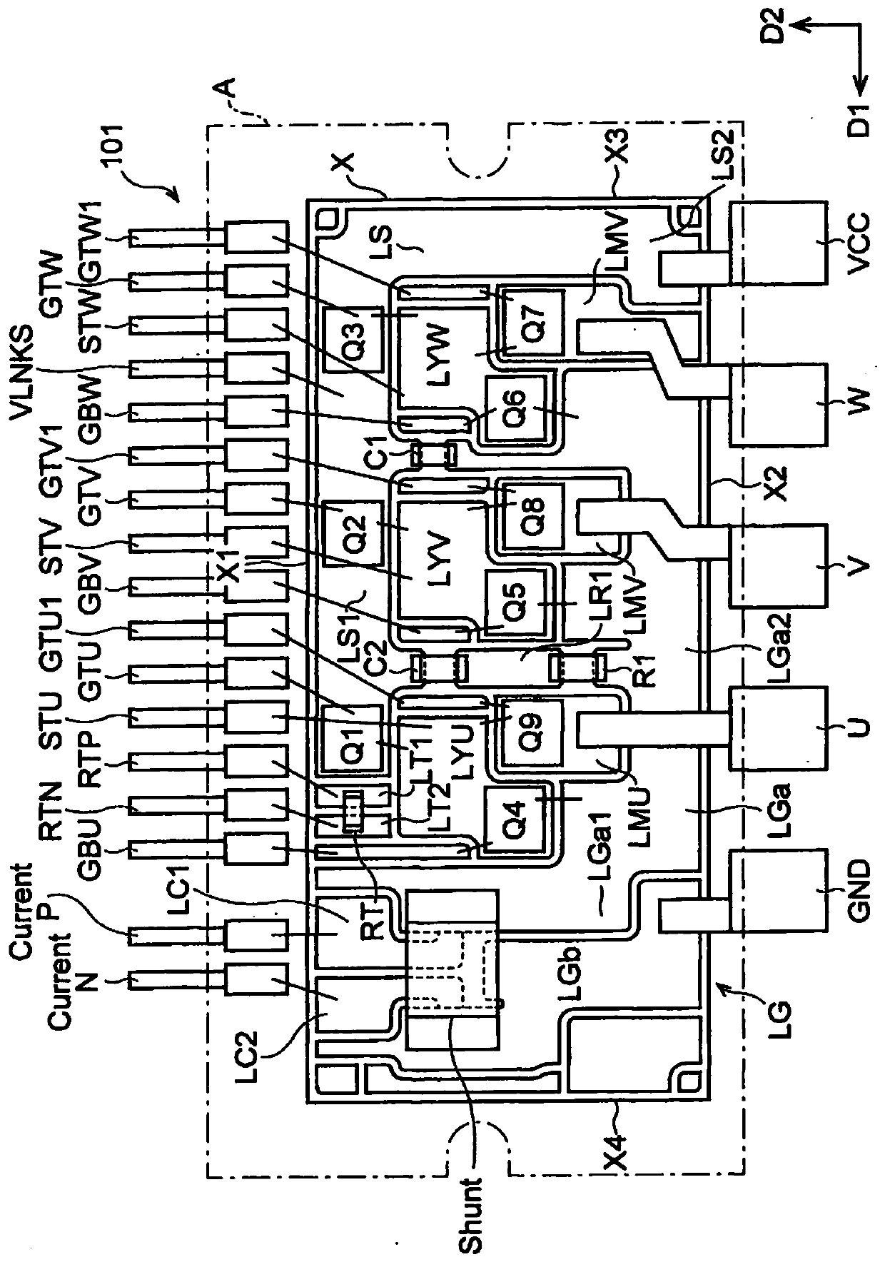
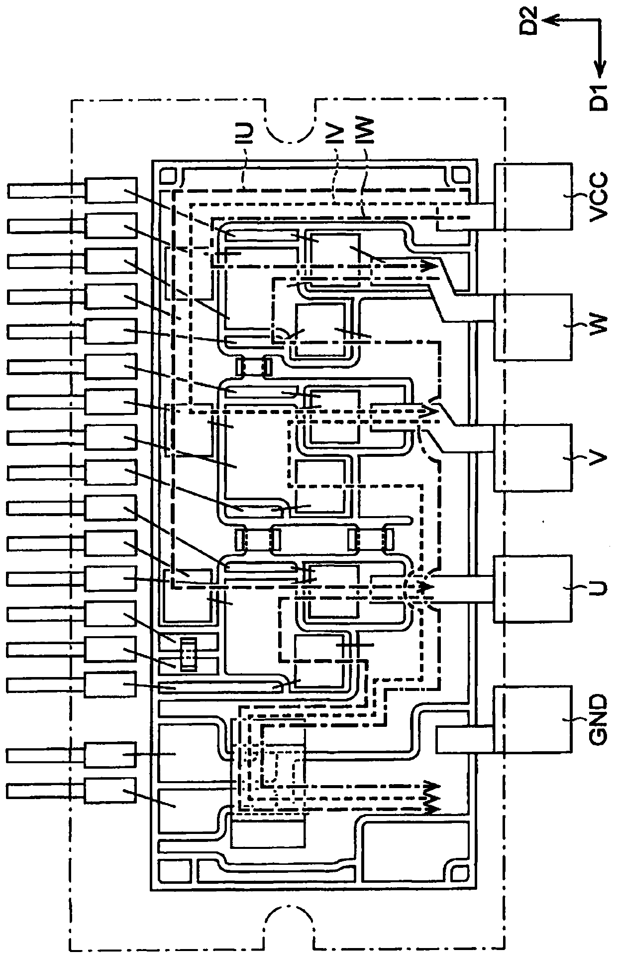
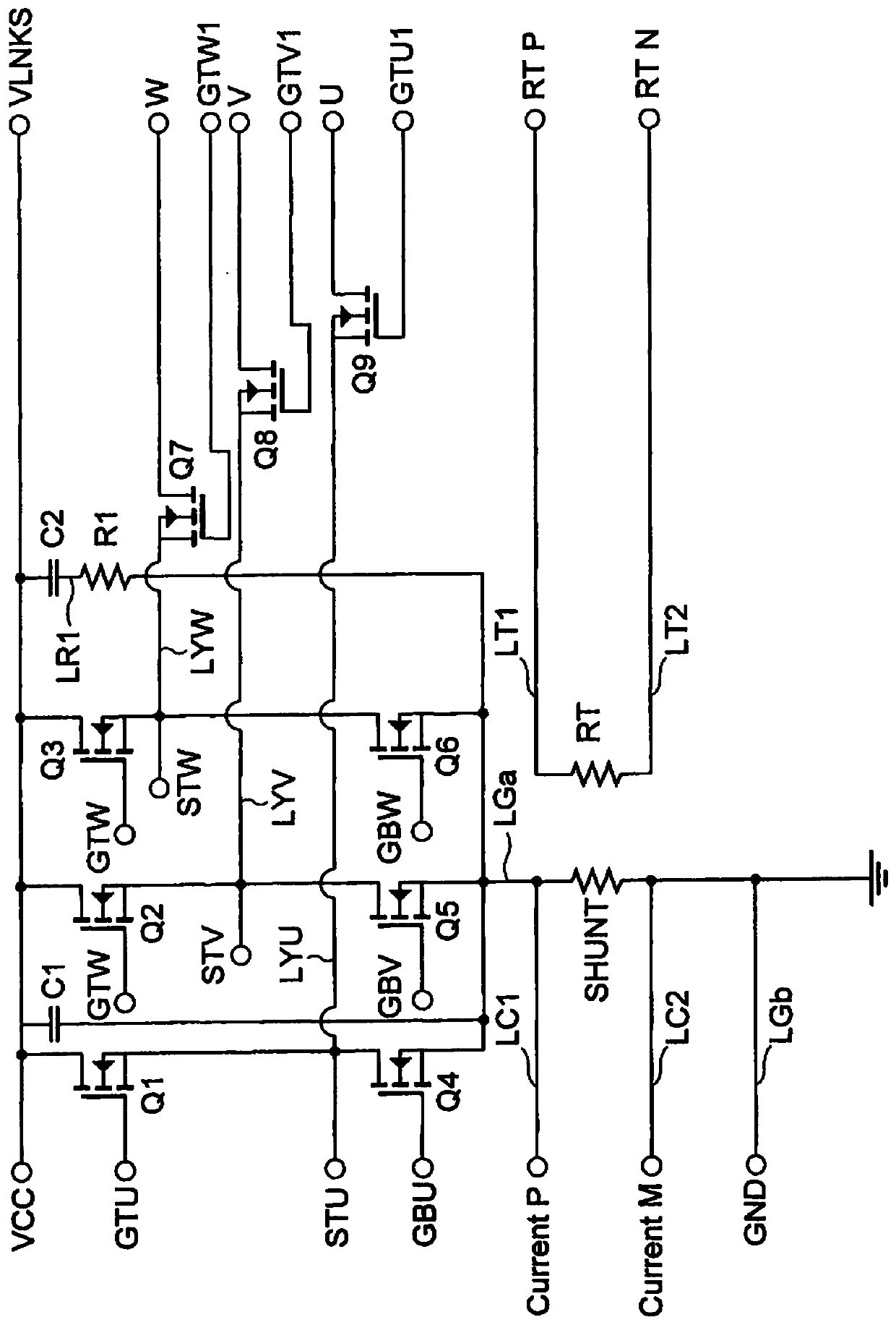
[0080] figure 1 It is a top view showing an example configuration of the electronic module 100 according to the first embodiment. figure 2 is to show figure 1 A schematic diagram of an example of a current path of the electronic module 100 is shown. image 3 is to show figure 1 It is a circuit diagram of an example of the circuit configuration of the electronic module 100 shown. exist figure 1 as well as figure 2 , the packaging component A is made transparent. In addition, in figure 2 , for simplicity, omitted figure 1 part of the symbols.

[0081] The electronic module 100 involved in the first embodiment is, for example, an inverter device (Inverter) for converting direct current into three-phase alternating current and providing the three-phase alternating current to a three-phase motor for driving.

[0082] Such as Figure 1 to Figure 3 As shown, the electronic module 100 includes: a substrate X; a plurality of signal terminals 101; a power supply wiring LS; ...

Embodiment 2

[0161] In the first embodiment described above, although the first to third high-side switches Q1, Q2, Q3, the first to third low-side switches Q4, Q5, Q6, and the first to third output switches Q9, Q8 and Q7 are nMOSFETs as an example ( image 3 ) has been described, but other semiconductor elements can also be applied.

[0162] That is, instead of these first to third high-side switches Q1, Q2, Q3, first to third low-side switches Q4, Q5, Q6, and first to third output switches, semiconductor elements such as pMOSFETs or others may be used. Q9, Q8, and Q7 thereby perform the same function.

[0163] In addition, in the second embodiment, the configurations of other electronic modules are the same as those in the first embodiment.

[0164] To sum up, the electronic module involved in one form of the present invention is used to convert direct current into three-phase alternating current, and provide the three-phase alternating current to a three-phase motor for driving. It is...


PUM


Abstract

This electronic module is provided with a power supply wire which is provided along a first side on a substrate and which is connected to a power supply terminal, a ground wire which is provided alonga second side on the substrate and which is connected to a ground terminal, and a first through a third half bridge which are configured with a high-side switch and a low-side switch connected in series between the power supply wire and the ground wire, and which are connected at the connection point of the high-side switch and the low-side switch to a first through a third motor terminal, respectively, and are connected in parallel to each other, wherein the first motor terminal, the second motor terminal and the third motor terminal are arranged between the power supply terminal and the ground terminal.

Description

technical field [0001] The invention relates to an electronic module. Background technique [0002] Conventionally, as a semiconductor device, an electronic module that converts DC power input from a DC power supply to AC power and outputs it has been widely known. [0003] The electronic module, for example, converts the DC voltage into a three-phase AC voltage for driving a three-phase motor (for example, refer to JP-A-2016-197985 and JP-A-2015-020368). [0004] In such a conventional electronic module, the layout from the power supply terminal to the ground terminal after passing through the power supply wiring of each phase, the high-side switch and low-side switch of each phase, and the ground wiring is divided by each phase, so the motor current ( The current path of the induced current) is different. [0005] That is, the length of the current path of the motor current flowing from the power supply terminal to the ground terminal after passing through the power supp...

Claims


Application Information

Patent Timeline
Patent Type & Authority Applications(China)
IPC IPC(8): H02M7/48H02P27/06
CPCH02P27/06H02M7/48H01L25/07H01L25/18H03K17/0814H03K17/162H01L2224/48247H01L2224/48227H01L2924/19105H01L2924/19107H02K11/33H01L23/5286H03K17/08142
Inventor 神山悦宏
Owner SHINDENGEN ELECTRIC MFG CO LTD
Learn More