
A Diagnosis Method for Simultaneous Faults of Actuator and Sensor in Control System

A technology of control system and diagnosis method, applied in general control system, control/adjustment system, test/monitoring control system, etc., to achieve simplified process and reduced interference

Active Publication Date: 2022-04-05
NANJING UNIV OF AERONAUTICS & ASTRONAUTICS
View PDF7 Cites 0 Cited by
  • Summary
  • Abstract
  • Description
  • Claims
  • Application Information

AI Technical Summary

Problems solved by technology

At present, the fault diagnosis method of the sensor is relatively complicated. This method can greatly simplify the diagnosis process when only the sensor fault occurs in the system.
But this technology does not have a solution for systems where both actuator failure and sensor failure occur simultaneously

Method used


Image

  • A Diagnosis Method for Simultaneous Faults of Actuator and Sensor in Control System
  • A Diagnosis Method for Simultaneous Faults of Actuator and Sensor in Control System
  • A Diagnosis Method for Simultaneous Faults of Actuator and Sensor in Control System

Examples


Embodiment Construction

[0061] Below in conjunction with accompanying drawing, technical scheme of the present invention is described in further detail:

[0062] This invention may be embodied in many different forms and should not be construed as limited to the embodiments set forth herein. Rather, these embodiments are provided so that this disclosure will be thorough and complete, and will fully convey the scope of the invention to those skilled in the art. In the drawings, components are exaggerated for clarity.
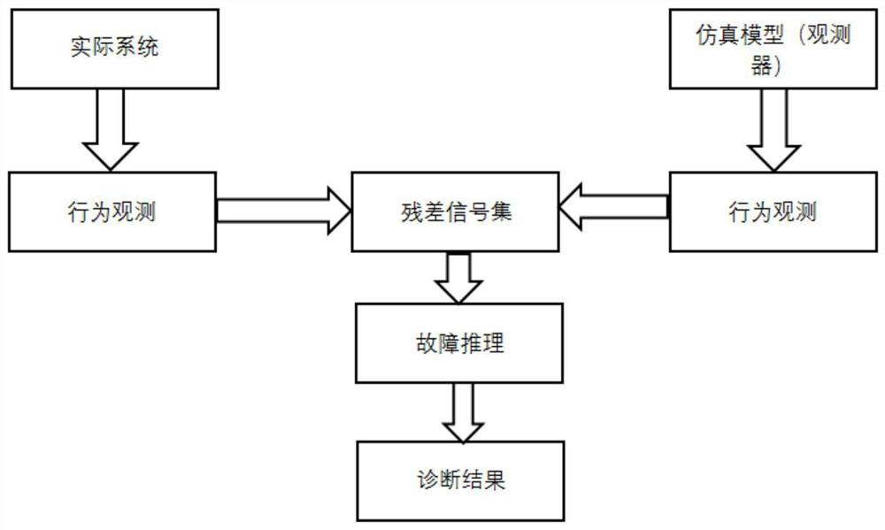
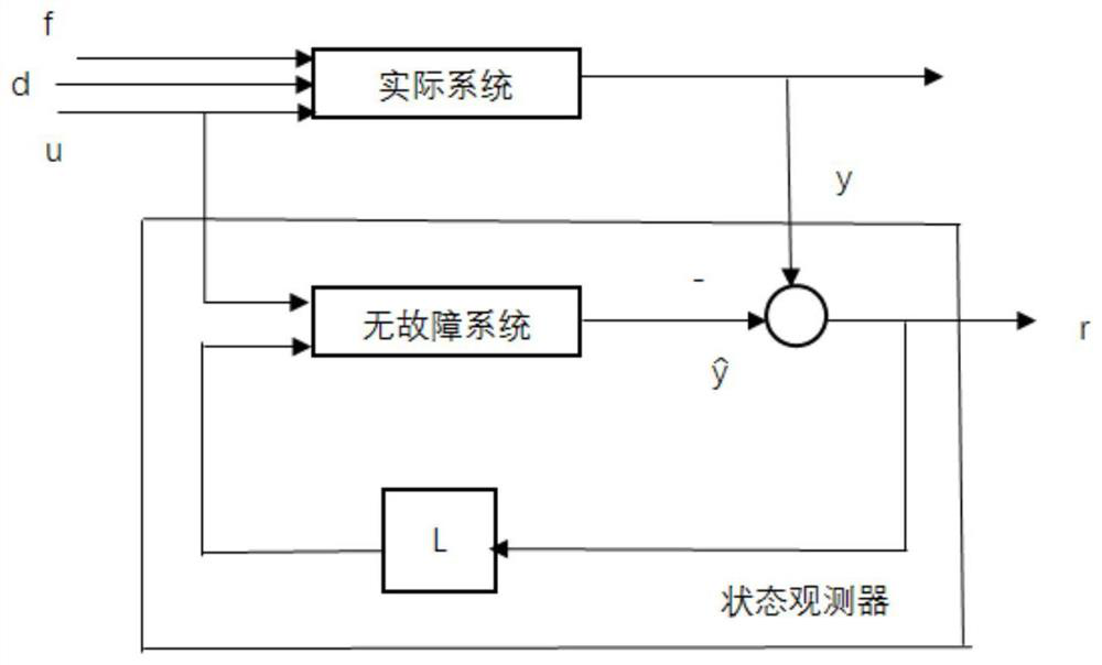
[0063] The core idea of ​​the fault diagnosis method studied by the present invention is to estimate the system output by constructing an observer, and then compare it with the output measurement value to obtain residual error information. Therefore, this is a method that focuses on the process of residual error acquisition, and at the same time, it is designed to make the residual error have the directionality corresponding to the fault, so as to carry out fault isolation and evaluati...


PUM


Abstract

The invention discloses a diagnosis method for simultaneous faults of actuators and sensors in a control system. Firstly, the fault model of the sensor is converted into the fault model of the actuator, and the fault diagnosis scheme of the actuator is modified to solve the fault of the false actuator. Diagnose the problem; then, when there are actuator and sensor faults in the system at the same time, the sliding mode observer of the pseudo-actuator fault diagnosis scheme is combined with the sliding mode observer suitable for common actuator faults, acting on the system, through Analyze residuals to complete fault diagnosis.

Description

technical field [0001] The invention relates to actuator diagnosis technology, in particular to a diagnosis method for simultaneous faults of actuators and sensors in a control system, which is mainly used for fault analysis of common automatic control systems under the condition of simultaneous faults of actuators and sensors. Background technique [0002] The two background technologies mainly involved in this paper are actuator diagnosis technology based on sliding mode observer (Reference: Liu Jingjin. Fault diagnosis technology based on sliding mode observer and its application in flight control system[D] .Nanjing: School of Automation, Nanjing University of Aeronautics and Astronautics, 2008), and a scheme to transform sensor faults into actuator fault models (references: Huang Yishan, Zhang Changfan, Yan Min. Multi-sensor fault diagnosis method based on sliding mode observer [J]. Journal of Dynamics and Control, 2011,09(4):378-384). [0003] The former is a fault dia...

Claims


Application Information

Patent Timeline
Patent Type & Authority Patents(China)
IPC IPC(8): G05B23/02
CPCG05B23/0275G05B2219/24065
Inventor 万怡仕肖玲斐
Owner NANJING UNIV OF AERONAUTICS & ASTRONAUTICS
Learn More