Container lifting spreader
A container and hanger technology, which is used in hoisting devices, transportation and packaging, load hanging components, etc., can solve the problems of cumbersome loading operations, improve loading efficiency, avoid jamming, and simplify the structure of the hanger. Effect
- Summary
- Abstract
- Description
- Claims
- Application Information
AI Technical Summary
Problems solved by technology
Method used
Image


Examples
Embodiment 1
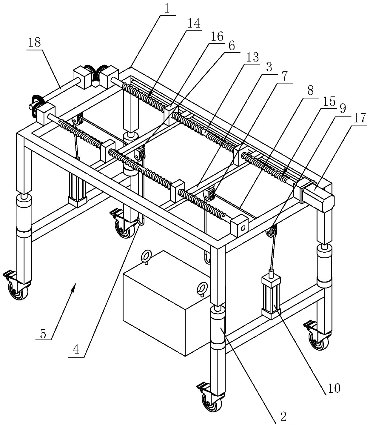
[0037] A container hanger, such as figure 1 As shown, it includes a rectangular frame-shaped top frame 1, the top frame 1 is made of steel, and the four corners on one side of the top frame 1 are fixed with telescopic struts 2 for driving the top frame 1 up and down, and the middle section of the telescopic strut 2 A hydraulic cylinder section is provided to realize the telescoping performance of the telescopic strut 2, and the end of the telescopic strut 2 away from the top frame 1 is rotatably connected with a roller, which is convenient for the present invention to be pushed in the path between narrow containers. The top frame 1 is slidingly connected with two slide bars 3 along the length direction of the top frame 1. The slide bars 3 are parallel to the width direction of the top frame 1. The slide bar 3 is movably provided with a hook 4 for lifting the container. Between the adjacent telescopic struts 2, all are arranged to facilitate the transport vehicle to drive into ...
Embodiment 2
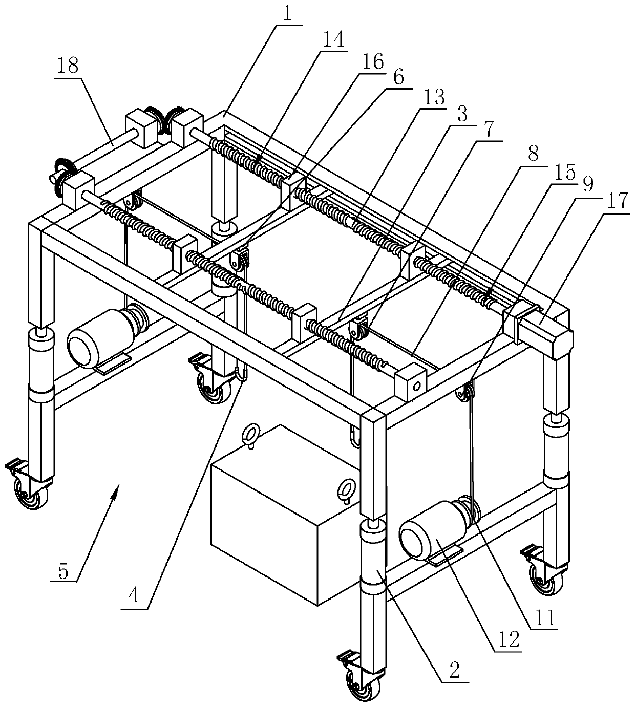
[0042] A container hanger, such as figure 2As shown, the difference from Embodiment 1 is that the adjustment assembly includes a guide wheel 9 hingedly connected to the top frame 1, and the end of the suspension rope 8 away from the hook 4 goes around the fixed pulley 7 and the circumference of the guide wheel 9 successively, A rope take-up roller 11 is connected, and the rope take-up roller 11 is connected with a drive motor 12 through transmission. Compared with the first embodiment, the stroke distance of the hydraulic cylinder is limited, so it cannot meet the requirement of high container lifting. Lifting itinerary.
Embodiment 3
[0044] A container hanger, such as image 3 As shown, the difference from Embodiment 1 is that the adjustment assembly includes a rope take-up roller 11 rotatably arranged on the top frame 1, and the rope take-up roller 11 is arranged on the top frame 1 and is located between two slide bars 3, One end of the two suspension ropes 8 away from the suspension hook 4 is fixed on the side wall of the rope take-up roller 11 . During use, the rope take-up roller 11 simultaneously drives the suspension ropes 8 on both sides to ensure that the suspension ropes 8 on both sides are rolled up at the same speed, and the lifting speed of the suspension hook 4 is also the same, thereby ensuring that the container can be lifted smoothly. On the top frame 1, a sliding rod 19 is parallelly fixed on both sides of the rope receiving roller 11. The sliding rod 19 is reciprocally slidingly connected with a guide wheel 20, and the suspension rope 8 is wound around the guide wheel 20. The leading scr...
PUM
 Abstract
Description
Claims
Application Information
 - R&D
- Intellectual Property
- Life Sciences
- Materials
- Tech Scout
- Unparalleled Data Quality
- Higher Quality Content
- 60% Fewer Hallucinations
Browse by: Latest US Patents, China's latest patents, Technical Efficacy Thesaurus, Application Domain, Technology Topic, Popular Technical Reports.
© 2025 PatSnap. All rights reserved.Legal|Privacy policy|Modern Slavery Act Transparency Statement|Sitemap|About US| Contact US: help@patsnap.com