
Steel pipe flaring and necking equipment and steel pipe flaring and necking method

A technology for steel pipes and equipment, applied in the field of steel pipe forming equipment, can solve the problems that the device can only be manually loaded, cannot guarantee the positioning of the workpiece, and the processing efficiency is low. The effect of efficiency

Inactive Publication Date: 2019-10-22
杨立夸
View PDF1 Cites 2 Cited by
  • Summary
  • Abstract
  • Description
  • Claims
  • Application Information

AI Technical Summary

Problems solved by technology

The existing steel pipe flaring and shrinking have the following problems: (1) Since there is no feeding device and discharging device, the device can only be manually loaded and discharged, and the efficiency is low; (2) Since there is no clamping device, the positioning of the workpiece cannot be guaranteed when the workpiece expands and shrinks; (3) Since the device has only one workpiece processing position, the processing efficiency is low

Method used


Image

  • Steel pipe flaring and necking equipment and steel pipe flaring and necking method
  • Steel pipe flaring and necking equipment and steel pipe flaring and necking method
  • Steel pipe flaring and necking equipment and steel pipe flaring and necking method

Examples


Embodiment Construction

[0023] specific implementation plan

[0024] The following will clearly and completely describe the technical solutions in the embodiments of the present invention with reference to the drawings in the embodiments of the present invention.

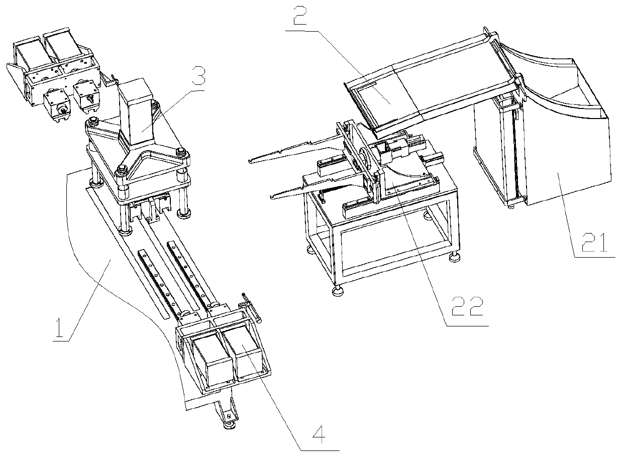
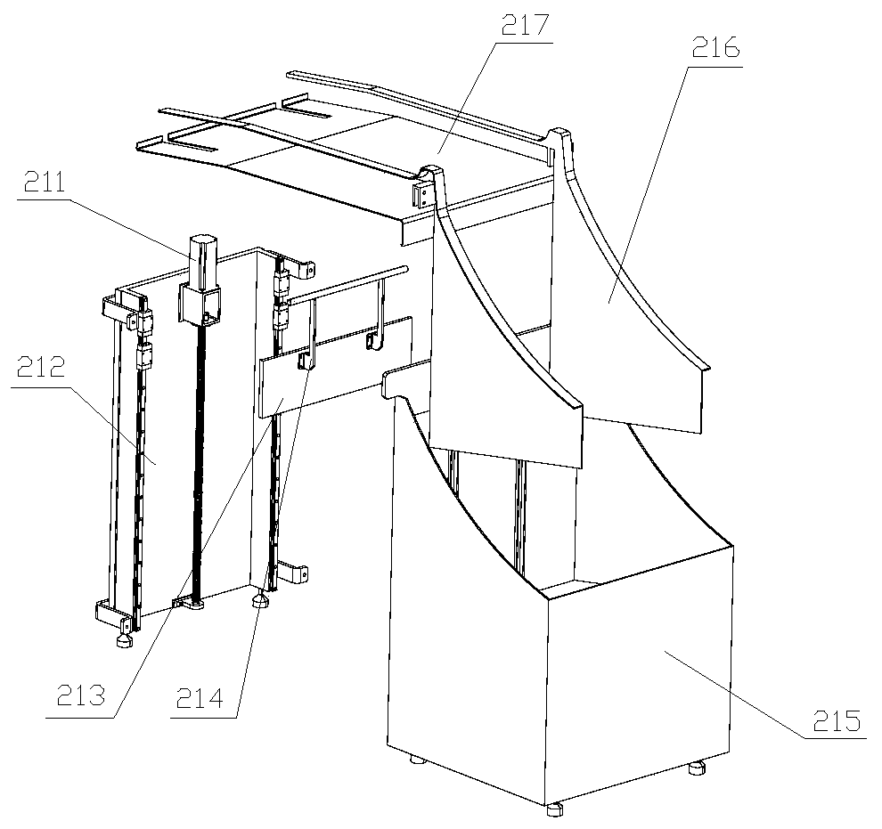
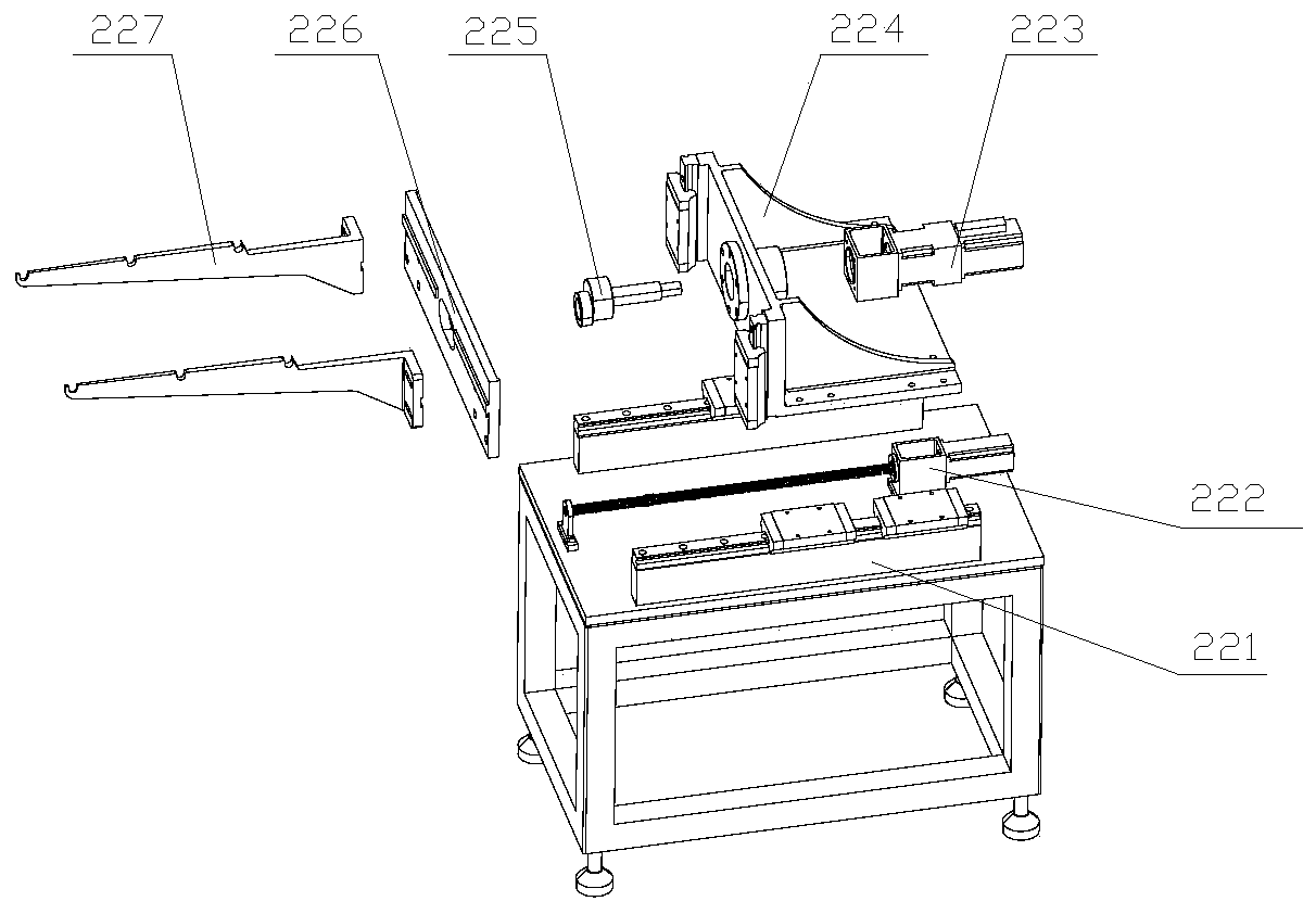
[0025] Such as figure 1 A steel pipe expansion and contraction device shown includes a frame 1 , a feeding device 2 , a clamping device 3 and a expansion and contraction device 4 . The clamping device 3 and the expansion and contraction device 4 are installed on the frame 1; the feeding device 2 is connected with the clamping device 3, and the feeding device 2 is used for feeding the steel pipe to be processed, and the expansion and contraction is completed on the clamping device 3 The operated steel pipe is sent out. The clamping device 3 is used to clamp and fix the steel pipe to be processed delivered by the feeding device 2. There are two expansion and contraction devices 4, the clamping device 3 is located between the two expansion ...


PUM


Abstract

The invention relates to the field of steel pipe forming equipment. steel pipe flaring and necking equipment comprises a rack, a feeding device, a clamping device and a flaring and necking device; theclamping device and the flaring and necking device are arranged on the rack; the feeding device is connected with the clamping device, and the feeding device is used for feeding a to-be-processed steel pipe and conveying the flared or necked steel pipe on the clamping device out; the clamping device is used for clamping and fixing the to-be-processed steel pipe conveyed by the feeding device; andthe flaring and necking device performs flaring or necking operation on the steel pipe on the clamping device. The steel pipe flaring and necking equipment has the advantages that the loading and unloading of steel pipes can be automatically completed, and the flaring and necking operations are convenient and efficient.

Description

technical field [0001] The invention relates to the field of steel pipe forming equipment, in particular to a steel pipe flaring and shrinking equipment. Background technique [0002] When the two ends of the stainless steel pipe are connected with other workpieces, it is necessary to expand and shrink the mouth of the steel pipe. At present, the flaring operation of the nozzle of the steel pipe is usually performed by shaking the extrusion die with a rocker to squeeze and expand the hole, resulting in unstable product quality of the flared steel pipe, low work efficiency, and easy cracking of the nozzle. Existing operating equipment such as Chinese Patent Application No. CN201720239747.1 discloses a steel pipe flaring and shrinking device. When the flared workpiece needs to be shrinked, the flared workpiece is sleeved from the through hole on the working surface. Outside the flaring mould, and the flaring workpiece is fixed, the power device drives the flaring jig to move ...

Claims


Application Information

Patent Timeline
Patent Type & Authority Applications(China)
IPC IPC(8): B21D41/02B21D41/04
CPCB21D41/02B21D41/04
Inventor 杨立夸张小会李秋琴
Owner 杨立夸
Learn More