
A method for detecting a motor rotor

A technology of motor rotor and detection method, which is applied in the direction of machine/structural component testing, static/dynamic balance testing, measuring devices, etc., which can solve problems such as bending, deformation, and pass rate of motor shafts and other accessories, so as to ensure delivery Quality, enhancement of contact area, effect of ensuring quality

Active Publication Date: 2021-08-10
衢州市迈德电子有限公司
View PDF10 Cites 0 Cited by
  • Summary
  • Abstract
  • Description
  • Claims
  • Application Information

AI Technical Summary

Problems solved by technology

[0002] After the motor rotor is produced, it needs to be assembled with various accessories, and the assembly process needs to be assembled with the interference fit of the air machine. After assembly, the motor shaft and other accessories sometimes appear bent or deformed. The qualification rate is affected, and it is necessary to provide a new detection method and supporting equipment for the assembled motor rotor

Method used


Image

  • A method for detecting a motor rotor
  • A method for detecting a motor rotor
  • A method for detecting a motor rotor

Examples


Embodiment 1

[0032] The invention discloses a detection method of a motor rotor, comprising the following steps:

[0033] S1 first rotor shaft runout detection: through the motor rotor runout detection device, the motor shaft is tested for circular runout;

[0034] S2 Finale: Press the rotor shaft that has passed the circular runout test into the inner hole of the rotor through a pneumatic press;

[0035] S3 The second round runout detection of the rotor shaft: the circular runout detection of the rotor shaft after the finale step;

[0036] S4 Rotor initial position detection: The position of the rotor on the rotor shaft is detected by the distance detection device installed on the circular runout detection device;

[0037] S5 Rotor binding force detection: through the detection of the rotor binding force detection device, the two ends of the rotating shaft are supported, and then the rotor is squeezed along the horizontal direction of the rotor shaft by the extrusion block, and the displ...

Embodiment 2

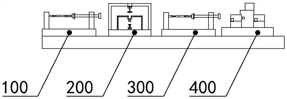
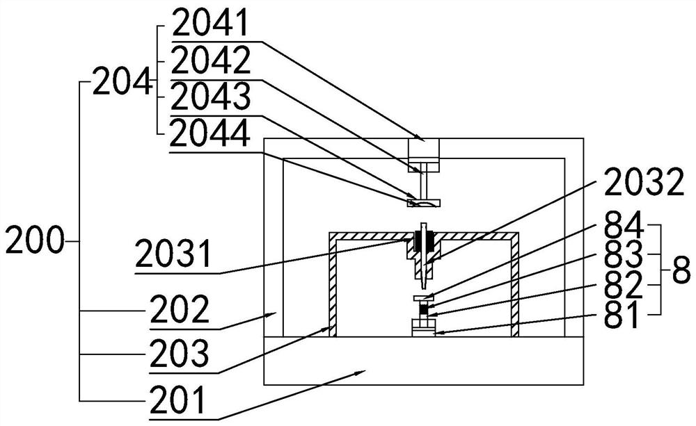
[0043] Such as Figure 1-Figure 5 As shown, the present invention also discloses a detection device for a motor rotor. In the specific embodiment of the present invention, according to the preparation sequence, it includes a circular runout detection device 100, a distance detection device 200, a rotor binding force detection device 300, and a displacement detection device 400. And the rotor dynamic balance testing machine 500.

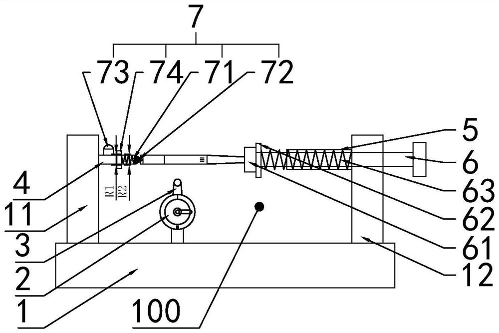
[0044] In a specific embodiment of the present invention, the circular runout detection device 100 includes a first base 1, a measuring gauge 2, and a first clamping seat 11 and a second clamping seat installed on both sides of the upper surface of the first base 1 12. The measuring gauge 2 is equipped with a circular runout measuring head 3, the measuring gauge 2 is installed vertically on the first base 1, and the circular runout measuring head 3 faces upwards; the inner side of the first clamping seat 11 is equipped with a tip 4 , a sleeve 5 is in...


PUM


Abstract

The invention relates to the technical field of rotor detection, in particular to a detection method and detection equipment for a motor rotor. It is characterized in that: according to the preparation sequence, it sequentially includes a circular runout detection device, a distance detection device, a rotor binding force detection device, a displacement detection device and a rotor dynamic balance testing machine. By increasing the invention, the invention has strong innovation and practicability, and is easy to popularize.

Description

technical field [0001] The invention relates to the technical field of rotor detection, in particular to a detection method and detection equipment for a motor rotor. Background technique [0002] After the motor rotor is produced, it needs to be assembled with various accessories, and the assembly process needs to be assembled with the mechanical interference fit of the air machine. After assembly, the motor shaft and other accessories sometimes appear bent or deformed, so its factory The qualification rate is affected, and it is necessary to provide a new detection method and supporting equipment for the assembled motor rotor. Contents of the invention [0003] In view of the deficiencies in the prior art, the object of the present invention is to provide a detection method and detection equipment for a motor rotor. [0004] The technical solution of the present invention is achieved in that a method for detecting a motor rotor comprises the following steps: [0005] S...

Claims


Application Information

Patent Timeline
Patent Type & Authority Patents(China)
IPC IPC(8): G01D21/02G01B21/00G01N19/04G01M1/38
CPCG01B21/00G01D21/02G01M1/16G01N19/04
Inventor 杜江赵传步张亮章龙卢怡成
Owner 衢州市迈德电子有限公司
Learn More