Self-locking lifting pen

A technology of self-locking and self-locking grooves, which is applied to pen holders, printing, writing utensils, etc., can solve the problems of cumbersome operation and non-self-locking, and achieve the effect of easy assembly, easy replacement of refills, and improved writing experience

Active Publication Date: 2019-10-18
温州市简系文具有限公司
View PDF10 Cites 7 Cited by
  • Summary
  • Abstract
  • Description
  • Claims
  • Application Information

AI Technical Summary

Problems solved by technology

[0004] The purpose of the invention is to provide a self-locking lifting pen in order to solve the problem that the existing pen operation mode is cumbersome and cannot be self-locking.

Method used


Image

  • Self-locking lifting pen
  • Self-locking lifting pen
  • Self-locking lifting pen

Examples


Embodiment 1

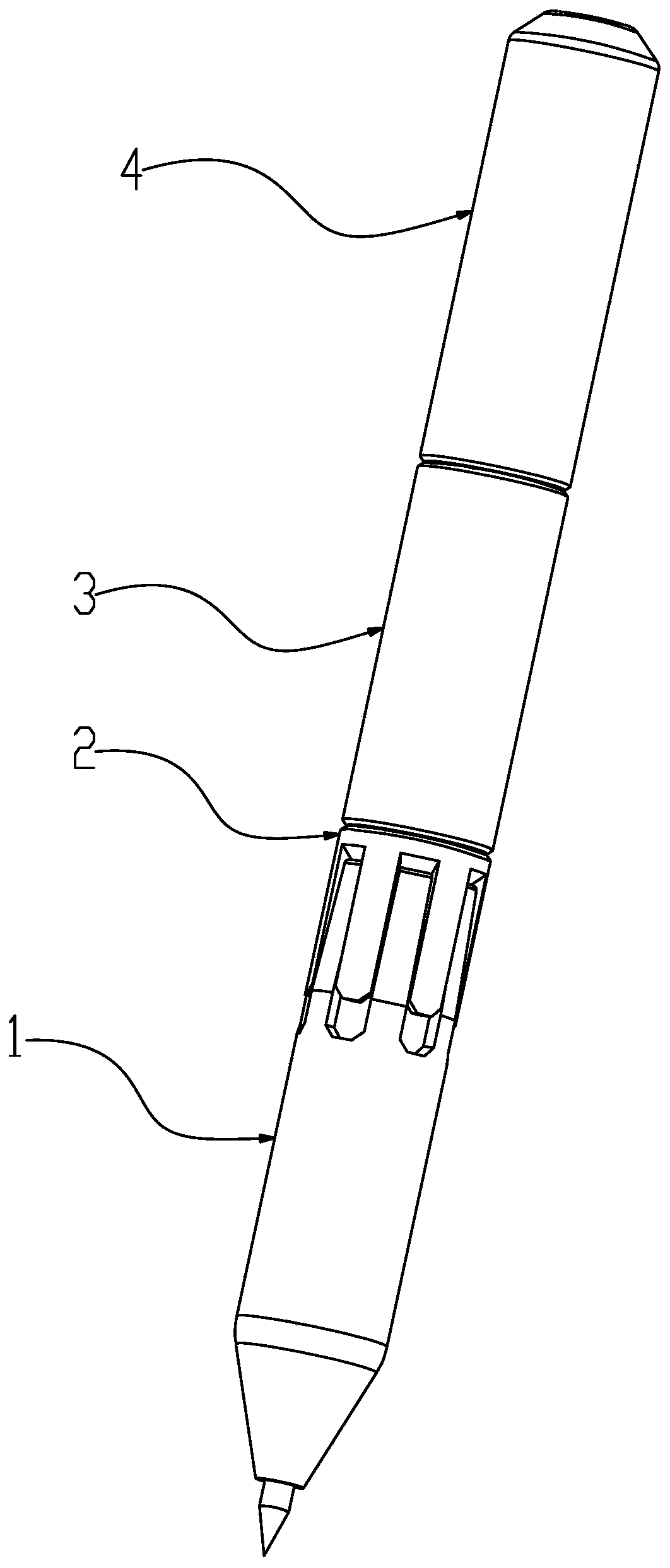
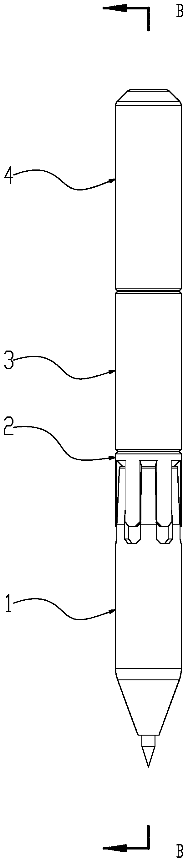
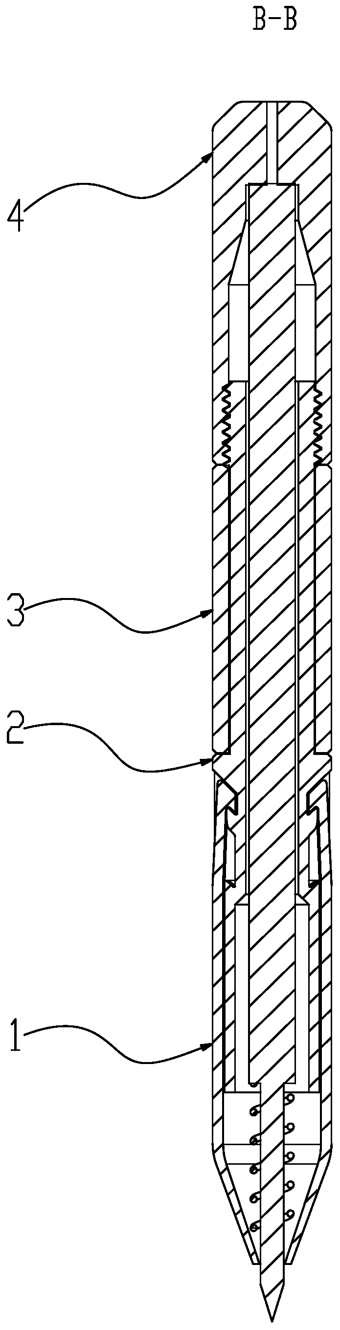
[0052] Such as Figure 1 to 5 The shown self-locking lifting pen includes a front tube 1, an inner rod 2, a pen core 5, a return spring 6 and a tail cover 4. As mentioned above, the return spring 6 is sleeved on the pen core 5, and the pen core 5 is sleeved with the return spring 6 in the front tube 1 and the inner rod 2. The tail cover 4 and the inner rod 2 are connected by threads.

[0053] The inner rod 2 is provided with an inner sliding contact portion 22 and one or more engaging slots 21. The inner sliding contact portion 22 is sleeved in the front cylinder 1. The above-mentioned engagement long groove 21 is composed of an anti-disengagement protrusion 211, a stationary groove 212, a hook protrusion 213, a matching groove 214, and a reset long slope 215 arranged in sequence.

[0054] The front cylinder 1 is extended with engaging columns 121 having the same number as the engaging long grooves 21. The engaging cylinder 121 is provided with an engaging inner protrusion 1211....

Embodiment 2

[0073] Such as Figure 6~12 The shown self-locking lifting pen includes a front tube 1, an inner rod 2, a pen core 5, a return spring 6 and a tail cover 4. As mentioned above, the return spring 6 is sleeved on the pen core 5, and the pen core 5 is sleeved with the return spring 6 in the front tube 1 and the inner rod 2. The tail cover 4 and the inner rod 2 are connected by threads.

[0074] The front cylinder 1 is divided into a lower cylinder 11 and an upper cylinder 12. The lower cylinder 11 and the upper cylinder 12 are connected by engagement, the lower cylinder 11 can freely rotate relative to the upper cylinder 12, and the upper cylinder 12 is extended with the same number of engaging slots 21. 合Column 121. The engaging cylinder 121 is provided with an engaging inner protrusion 1211. The above-mentioned engaging inner protrusion 1211 is moved and locked in the engaging long groove 21.

[0075] The inner rod 2 is provided with an inner sliding contact portion 22 and one or...


PUM


Abstract

The invention relates to a self-locking lifting pen comprising a front barrel, an inner rod, a cartridge, a reset spring and a tail cover. The reset spring is connected to the cartridge in a sleevingmanner. The cartridge and the reset spring are connected in the front barrel and the inner rod in a sleeving manner. The tail cover and the inner rod are connected through threads. The inner rod is provided with an inner slide contact part and one to multiple clamping long grooves. The inner slide contact part is connected in the front barrel in a sleeving manner. Each clamping long groove is formed by sequentially arranging an unhooking prevention lug, a standing groove, a use hook lug, a matching groove and a reset long slope. The front barrel is provided with clamping columns in an extending manner, wherein the number of the clamping grooves is consistent with that of the clamping long grooves. A clamping inner lug is arranged on each clamping column. The clamping inner lugs re movablyclamped in the clamping long grooves. The front barrel and the inner rod are connected in a clamping manner through movement clamping of the clamping inner lugs and the clamping grooves.

Description

Technical field [0001] The invention relates to a pen, in particular to a self-locking lifting pen. Background technique [0002] Nowadays, the rapid development of technology has continuously improved the quality of human life. However, the improvement and research on pens has stagnated. Although this is the era of intelligence, computers and mobile phones occupy human lives, but pens are The necessity of the traditional civilization recording method is still irreplaceable at present. [0003] The two most important points of writing tools are: first, the pen core; second, the structural design of the outer pen shell; for the above two points, humans have been making improvements and researches. The existing pen shell design technology is very mature, but , The operation method is single and the operation steps are many. Nowadays, ergonomics is emphasized. For the ergonomics of pens, most of them are only ergonomic improvements to the grip when writing; however, the most fundamen...

Claims


Application Information

Patent Timeline
IPC IPC(8): B43K24/02B43K3/00
CPCB43K3/00B43K24/02
Inventor 余成鹏
Owner 温州市简系文具有限公司
Why Eureka
Try Eureka