
New energy self-cleaning solar panel

A solar panel, self-cleaning technology, applied in the direction of photovoltaic power generation, electrical components, photovoltaic modules, etc., can solve the problem that solar panels cannot be dusted, and achieve efficient cleaning effect

Active Publication Date: 2019-10-15
中宏京(天津)智能科技有限公司
View PDF3 Cites 8 Cited by
  • Summary
  • Abstract
  • Description
  • Claims
  • Application Information

AI Technical Summary

Problems solved by technology

[0005] The purpose of the present invention is to provide a new energy self-cleaning solar panel that can use clean energy for dust removal to solve the above-mentioned problem that the traditional solar panels cannot remove dust

Method used


Image

  • New energy self-cleaning solar panel
  • New energy self-cleaning solar panel
  • New energy self-cleaning solar panel

Examples


Embodiment 1

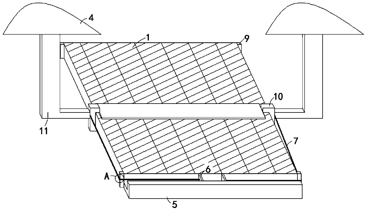
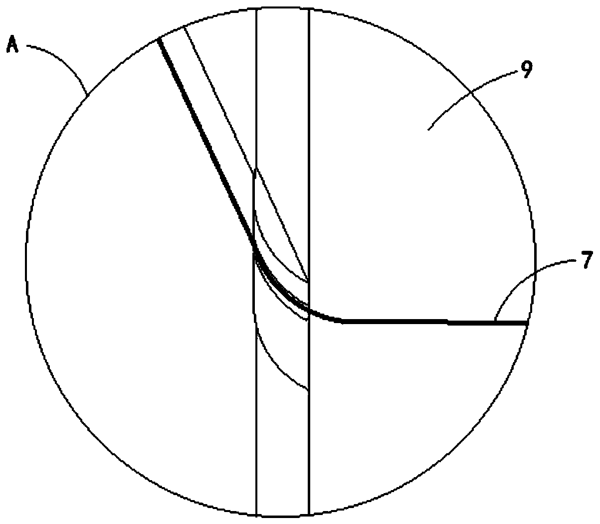
[0024] Such as Figure 1-4 As shown, a new energy self-cleaning solar panel includes a battery panel 1, the upper side wall of the battery panel 1 is slidably connected with a brush plate 2, and the left and right ends of the brush plate 2 are fixedly connected with a sliding mechanism 3, specifically Yes, the sliding mechanism 3 includes a U-shaped slider 10 engaged with the left and right sides of the battery panel 1, the U-shaped slider 10 is fixedly connected with an L-shaped connecting bar 11, and the upper end of the L-shaped connecting bar 11 is fixed to the wing plate 4 Connection, the other end of the sliding mechanism 3 is fixedly connected with a wing plate 4, which is in the shape of a wing, the upper edge is an upwardly arched arc line, and the lower edge is a horizontal line. , the wind will form a pressure difference on the upper and lower surfaces of the wing plate 4, that is, the pressure on the lower surface of the wing plate 4 is high, and the pressure on th...

Embodiment 2

[0028] Such as Figure 5-6 As shown, the difference between this embodiment and Embodiment 1 is that the reset mechanism 8 includes an elastic bellows 13, and the two ends of the elastic bellows 13 are respectively fixedly connected to the opposite side walls of the two dust-scraping boards 6, and the dust-scraping boards 6 is provided with an air hole communicating with the elastic bellows 13.

[0029] In this embodiment, when the brush plate 2 moves upward, the dust-scraping plates 6 will be driven to move to both sides, and the elastic bellows 13 will be inflated at this time. The pulling of 13 moves toward the middle part of the dust storage tank 5, and the gas in the elastic bellows 13 can be pressed out in this process, and is sprayed in the dust storage tank 5 to remove the accumulated dust inside it.


PUM


Abstract

The invention belongs to the technical field of new energy equipment and in particular to a new energy self-cleaning solar panel, comprising a solar panel. The upper side wall of the solar panel is slidably connected with a brush plate. The left and right ends of the brush plate are fixedly connected with sliding mechanisms. Wing plates are fixedly connected to the other ends of the sliding mechanisms. A dust receiving tank is fixedly connected to the lower side of the solar panel. Two dust scraping plates are slidably connected in the dust receiving tank. The side walls of the two dust scraping plates away from each other are both connected to connecting ropes. The other end of each connecting rope is fixedly connected with the corresponding sliding mechanism. A reset mechanism is arranged between the two dust scraping plates. The four corners of the solar panel are fixedly connected with stopping blocks. The wind energy is fully utilized by the wing plates, so that the brush plate slides up and down under the indirect driving of the wind energy so as to remove the dust from the surface of the solar panel, thereby improving the absorption of light energy by the solar panel. Further, this process utilizes clean and renewable wind energy and requires no external energy supply so as to achieve a clean and environment-friendly effect.

Description

technical field [0001] The invention belongs to the technical field of new energy equipment, and in particular relates to a new energy self-cleaning solar panel. Background technique [0002] Solar cells, also known as "solar chips" or "photocells", are photoelectric semiconductor sheets that use sunlight to generate electricity directly. A single solar cell cannot be used as a power source directly. As a power source, several single solar cells must be connected in series or in parallel. There are two ways of solar power generation, one is light-heat-electricity conversion, and the other is light-electricity direct conversion. [0003] Because the wind in a wide area is usually strong, and the wind will bring dust, so for a solar panel placed in a wide area, its surface is likely to be gradually covered by more dust, and the dust covers the components, and the overall The light transmittance of the photovoltaic system decreases. When the photovoltaic system is running, the...

Claims


Application Information

Patent Timeline
Patent Type & Authority Applications(China)
IPC IPC(8): H02S40/10
CPCH02S40/10Y02E10/50
Inventor 毛跃凯
Owner 中宏京(天津)智能科技有限公司
Learn More