Power-off self-locking motor system

A self-locking motor and self-locking technology, which is applied to the deceleration device of AC motor, electric motor/converter plug, deceleration device parts, etc., can solve the problems of manual unlocking and unlocking, and achieve safe operation and realization simple effect

Pending Publication Date: 2019-10-15
南京康尼智控技术有限公司
View PDF0 Cites 4 Cited by
  • Summary
  • Abstract
  • Description
  • Claims
  • Application Information

AI Technical Summary

Problems solved by technology

[0004] Purpose of the invention: The technical problem to be solved by the present invention is to provide a power-off self-locking motor system, which solves the problem that the current in-wheel motor system cannot be unlocked when the power is off, and can provide enough resistance

Method used


Image

  • Power-off self-locking motor system
  • Power-off self-locking motor system
  • Power-off self-locking motor system

Examples


Embodiment Construction

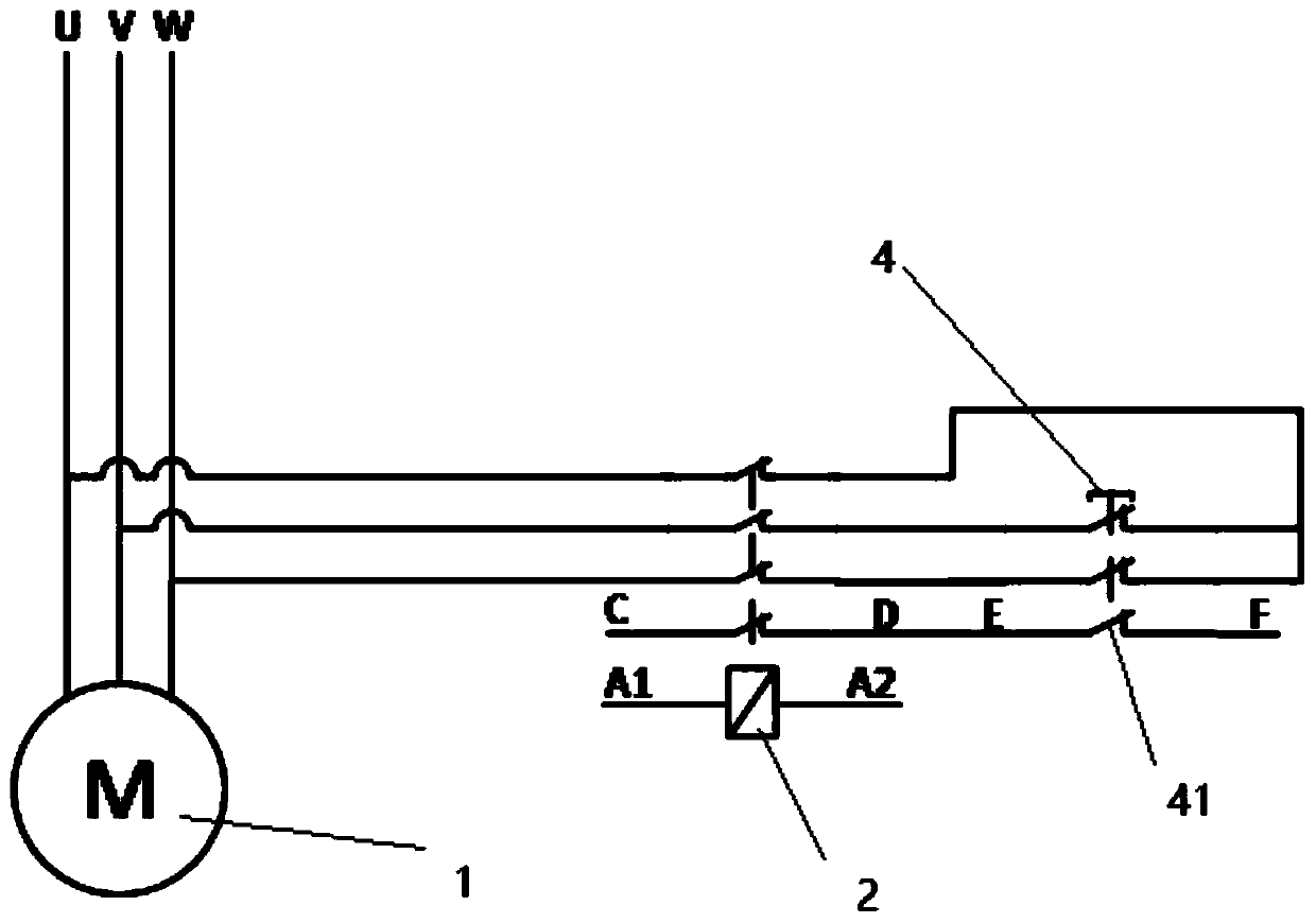
[0020] The power-off self-locking motor system of the present invention includes a hub motor 1, a driver and a power-off self-locking device, the power-off self-locking device includes a relay 2 connected to the phase line of the hub motor 1, and a coil control lead of the relay 2 The pin is connected to the driver, and the power-off self-locking device also includes an unlocking device connected in series with the relay 2, and the unlocking device is used to manually disconnect the circuit of the relay 2. This system mainly uses the normally closed contact of the monostable relay. If the DC brush motor is connected, its two phase lines are respectively connected to the two sets of normally closed contacts of the relay 2. If the DC brushless motor is connected , the three phase wires are respectively connected to the three sets of normally closed contacts of the relay 2, and the other ends of the above two or three sets of normally closed contacts are short-circuited. Realize ...


PUM


Abstract

The invention discloses a power-off self-locking motor system, comprising a hub motor, a driver and a power-off self-locking device. The power-off self-locking device comprises a relay connected to aphase line of the hub motor, and the coil control pin of the relay is connected to the driver. The power-off self-locking device further includes an unlocking device connected in series to the relay,and the unlocking device is used for manually disconnecting the line of the relay. The deficiency that the current hub motor system can not be unlocked when the power is off can be solved, sufficientresistance can be provided in the power-off case to enable the speed of the motor to be reduced to a controllable state, the risk caused by stall can be reduced, manual unlocking can also be carried out, the power-off implementation function requirement is met, and an unlocking state detection function can also be provided like a mechanical brake.

Description

technical field [0001] The invention relates to a motor system, in particular to a power-off self-locking motor system. Background technique [0002] In equipment that uses in-wheel motors (DC brushed motors or DC brushless motors) as power output, especially electric wheelchairs, elderly scooters, electric vehicles, AGVs or logistics vehicles, etc., if an accident occurs when it is on a slope In the case of power failure, if there is no braking device, there will be dangerous situations such as stalling. Therefore, it is very necessary to add a power failure self-locking device to the above equipment. For example, in the industry of electric wheelchairs or scooters for the elderly, mechanical brakes are generally used as power-off self-locking mechanisms. Although using brakes as power-off self-locking mechanisms can provide better braking effects when power is off, the cost High, complex installation methods, generally require the motor to use a gearbox and provide a cert...

Claims


Application Information

Patent Timeline
IPC IPC(8): H02P3/02H02P3/22
CPCH02P3/02H02P3/22
Inventor 费凯成王驰金彪罗浩珏
Owner 南京康尼智控技术有限公司
Why Eureka
Try Eureka