
Single-free-surface combined blast hole broaching blasting method

A technology of blasting and slotting, which is applied to the field of single-free-surface combined blasting slotting blasting, can solve the problems of large amount of charge in a single blasting section, adverse effects of surrounding rock mass and facilities and equipment, etc., to achieve blasting vibration reduction, reduce Blasting vibration effect, the effect that is conducive to rock crushing

Inactive Publication Date: 2019-10-15
CENT SOUTH UNIV
View PDF9 Cites 4 Cited by
  • Summary
  • Abstract
  • Description
  • Claims
  • Application Information

AI Technical Summary

Problems solved by technology

Affected by the construction accuracy of the drilling rig, the blastholes in the deep hole cut blasting inevitably have different degrees of deflection. The common cutting blasting method is to combine several blastholes into combined blastholes and blast at the same segment, and use the interaction between the explosion stress wave and the blasting gas between the combined blastholes to form a common blasting funnel. However, since there is only one free surface , and the single-stage blasting charge is large, the cutting blasting method often causes strong vibration effects, which adversely affects the surrounding rock mass and facilities and equipment

Method used


Image

  • Single-free-surface combined blast hole broaching blasting method
  • Single-free-surface combined blast hole broaching blasting method
  • Single-free-surface combined blast hole broaching blasting method

Examples


Embodiment

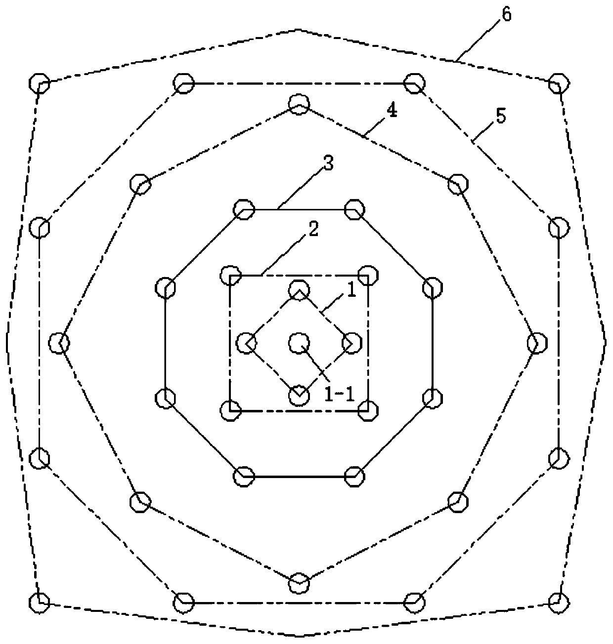
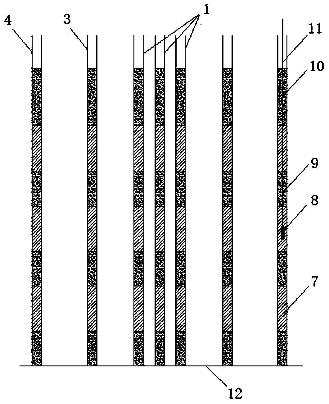
[0027] see Figure 1-3 , the figure shows the specific implementation of the single free surface combined blast hole slotting blasting method of the present invention.

[0028] Specific as figure 1 As shown, in this embodiment, six circles of combined blastholes are arranged in the groove blasting area. The arrangement steps of combined blastholes are as follows: firstly, a central blasthole 1-1 is set in the middle of the slotting blasting area, and a circle of four blastholes arranged in a square orientation is set around the center blasthole, and the above five blastholes form The first circle of combined blastholes 1; outside the first circle of combined blastholes 1, a circle of four blastholes arranged in a square orientation is set around the center blasthole 1-1 to form a second circle of combined blastholes 2; then Three circles of combined blastholes arranged in regular octagonal orientations are gradually set outward with the center blasthole 1-1 as the center, fo...


PUM


Abstract

The invention discloses a single-free-surface combined blast hole broaching blasting method. The method comprises the steps that a blasting center hole and a plurality of circles of combined blast holes around the blasting center hole with different distances are arranged, the blast holes are charged in a sectioned mode and independently controlled to detonate, all the blast holes are subjected tosubsection delay blasting from bottom to top according to the explosive sections, and the delay blasting of the same section of explosive is completed by all the combined blast holes in a mode from inside to outside by taking the center blast hole as a starting point within blasting delay of the two sections of explosive in the center blast hole. According to the method, the combined delay initiation between the blast holes and in the blast holes is adopted, so that a common blasting funnel is formed, the broaching blasting effect is guaranteed, the action time of the pressure of the blastinggas in the combined blast holes is prolonged, more energy can be applied to the subsequent rock pushing and throwing, the explosive quantity of a single section of blasting can be greatly reduced, and the defect of large vibration of a traditional cut blasting in the same section is avoided.

Description

technical field [0001] The invention belongs to mine blasting technology, and in particular relates to a single free surface combined blast hole slotting blasting method. Background technique [0002] The blasting condition of only one free surface is often encountered in trench blasting and raise excavation blasting projects in underground mines. Affected by the construction accuracy of the drilling rig, the blastholes in the deep hole cut blasting inevitably have different degrees of deflection. The common cutting blasting method is to combine several blastholes into combined blastholes and blast at the same segment, and use the interaction between the explosion stress wave and the blasting gas between the combined blastholes to form a common blasting funnel. However, since there is only one free surface , and the single-stage blasting charge is large, the cutting blasting method often causes strong vibration effects, which adversely affects the surrounding rock mass and ...

Claims


Application Information

Patent Timeline
Patent Type & Authority Applications(China)
IPC IPC(8): F42D1/08F42D3/04
CPCF42D1/08F42D3/04
Inventor 邱贤阳史秀志苟永刚喻智饶帝军霍晓峰陈辉王远来
Owner CENT SOUTH UNIV
Learn More