
Periphery hole charging structure for energy-gathered hydraulic pressure smooth blasting, and construction method thereof

A technology of smooth blasting and construction method, applied in blasting and other directions, can solve the problems of difficulty in generating high temperature and high pressure gas, inability to solve, and increase the extension and expansion of initial cracks in rocks, so as to achieve easy formation, sufficient expansion and extension, and reduce dust concentration. Effect

Pending Publication Date: 2019-10-15
CHINA RAILWAY 16TH BUREAU GRP CO LTD
View PDF4 Cites 21 Cited by
  • Summary
  • Abstract
  • Description
  • Claims
  • Application Information

AI Technical Summary

Problems solved by technology

[0004] However, conventional optical blasting blastholes use powder coils and blasting wires, and it is difficult to generate enough high-temperature and high-pressure gas during the explosion. The "water wedge" effect produced is not enough to promote the extension and expansion of the initial cracks in the rock, and it is also not conducive to the expansion of the existing cracks. The formed cracks extend and expand again, which cannot solve the problems existing in conventional smooth blasting

Method used

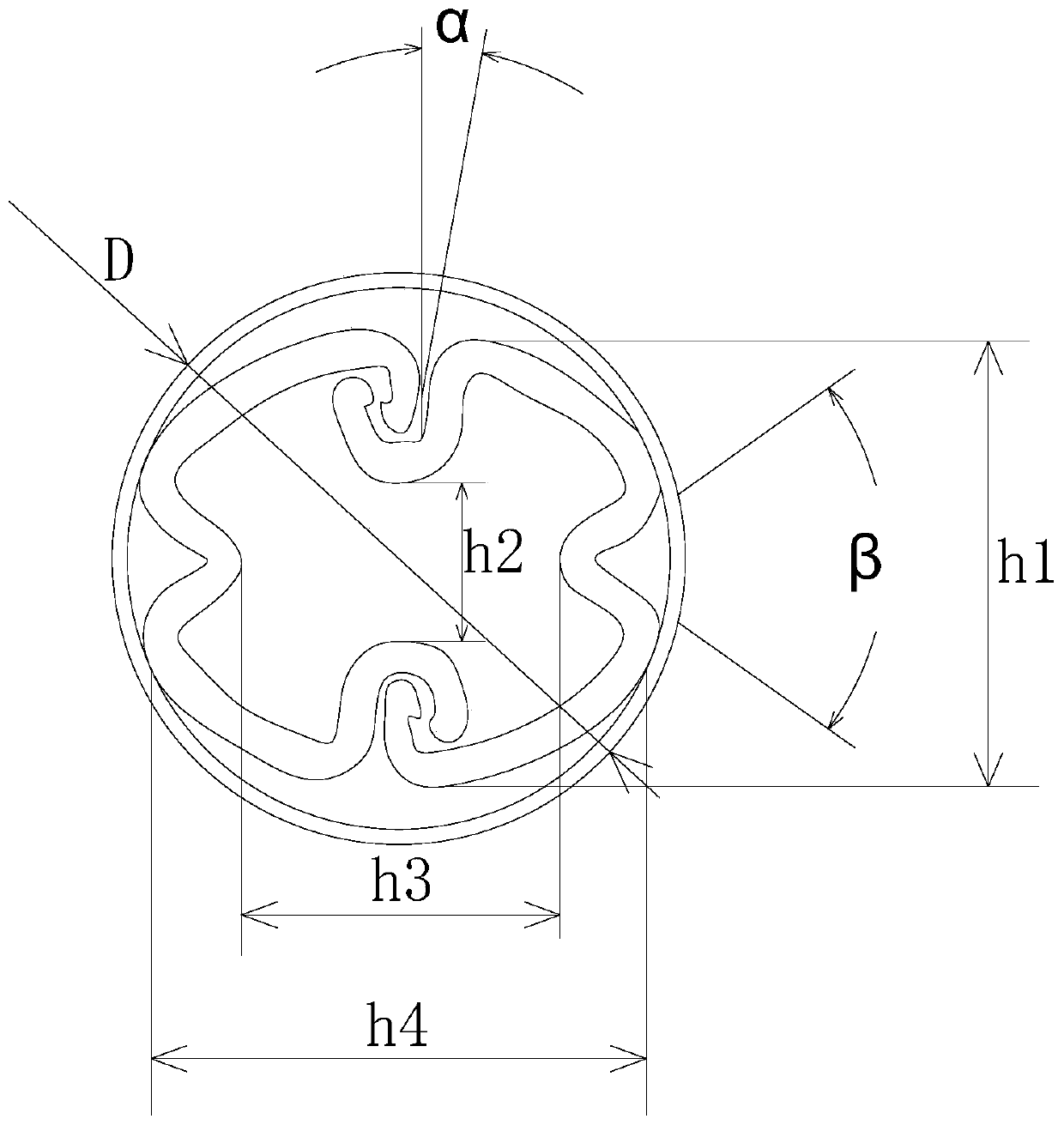

Image

  • Periphery hole charging structure for energy-gathered hydraulic pressure smooth blasting, and construction method thereof
  • Periphery hole charging structure for energy-gathered hydraulic pressure smooth blasting, and construction method thereof
  • Periphery hole charging structure for energy-gathered hydraulic pressure smooth blasting, and construction method thereof

Examples


Embodiment Construction

[0067] The technical solutions of the present invention will be further described below with reference to the accompanying drawings and specific embodiments.

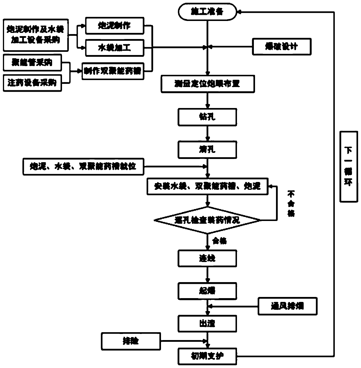
[0068] see figure 1 As shown, a peripheral eye charge structure for energy-gathering water pressure smooth blasting is composed of a blast hole and a water bag 1, an energy-concentrating tube charge bag 2 and a mud 3 arranged in the blast hole. Compared with conventional smooth blasting, the only difference is in the charge structure of the peripheral eye. The energy-gathering tube charge 2 is used to replace the traditional explosive, and the water bag 1 and the mud 3 are added. The depth of the blasthole is L, and the bottom of the blasthole is One water bag 1, the length of the water bag 1 at the bottom of the blasthole is L1, the length of the energy accumulating tube medicine bag 2 is L2, 0.65L≤L2≤0.75L, two water bags 1 in the middle of the blasthole, and two water bags 1 in the middle of the blasthole The length...


PUM


Abstract

The invention discloses a periphery hole charging structure for energy-gathered hydraulic pressure smooth blasting, and a construction method thereof, and belongs to the technical field of tunnel construction. The periphery hole charging structure for energy-gathered hydraulic pressure smooth blasting is formed by a shot hole, water bags, an energy-gathered pipe powder charge and a stemming, wherein the water bags, the energy-gathered pipe powder charge and the stemming are arranged in the shot hole; the bottom of the shot hole is a section of water bag; the middle part of the shot hole is twosections of water bags; the energy-gathered pipe powder charge is arranged between the water bag on the bottom of the shot hole and the water bags in the middle of the shot hole; the stemming is blocked in the shot hole; a high-temperature high-pressure gas produced by explosion produces a 'water wedge' effect through a jet flow formed in an energy-gathered groove and the water bags in the smoothblasting shot hole under a blasting action, so that a rock initial crack is promoted to extend, expand and enlarge; meanwhile, due to a composite blocking function of the water bags and the stemming,the formed crack is favorably extended, expanded and enlarged; and the water bags are placed in the smooth blasting shot hole, and a water spray formed in the blasting process further plays a role infalling dust, so that the ventilation time is reduced, the working environment is improved, and the body health of constructing personnel is protected.

Description

technical field [0001] The invention relates to the technical field of tunnel construction, in particular to a peripheral eye-charging structure and a construction method thereof for energy-gathering water pressure smooth blasting. Background technique [0002] With the rapid development of the economy and the continuous development of road construction, the construction of subways and tunnels is also in progress. When blasting projects, conventional smooth blasting is currently used. The construction principle of conventional smooth blasting is as follows: [0003] In engineering hydraulic blasting, due to the presence of water in the blasthole, the shock wave propagating in the water is incompressible to the water, and the explosion energy is transmitted to the surrounding rock of the blasthole through the water with almost no loss, which is very conducive to rock breaking; The "water wedge" effect is conducive to the further crushing of the rock; the gun mud is firmer and...

Claims


Application Information

Patent Timeline
Patent Type & Authority Applications(China)
IPC IPC(8): F42D1/00F42D1/08F42D3/04
CPCF42D1/00F42D3/04F42D1/08
Inventor 马栋李子强郭永忠苏庆国李国英杜鹏毅张奇刘世杰宋青波郭雷
Owner CHINA RAILWAY 16TH BUREAU GRP CO LTD
Learn More