Precision compensation type harmonic speed reducer

A harmonic reducer and precision compensation technology, which is applied to mechanical equipment, belts/chains/gears, transmission devices, etc., can solve problems such as large backlash, inability to assemble and rotate, and the precision life of the reducer cannot be too long.

Pending Publication Date: 2019-10-15
AICI TECH (NINGBO) CO LTD
View PDF0 Cites 0 Cited by
  • Summary
  • Abstract
  • Description
  • Claims
  • Application Information

AI Technical Summary

Problems solved by technology

[0005] However, the hysteresis of the current harmonic reducer depends on the degree of meshing tightness between the teeth of the ellipse major axis and the teeth of the steel wheel after the elliptical deformation of the flexspline under the action of the wave generator. If the meshing is not tight, the hysteresis will be large. Ying will not be able to assemble or rotate difficult. Whether the flex spline and steel wheel can be accurately meshed depends on the production accuracy of the harmonic reducer parts; at the same time, the flex spline, steel wheel and wave generator will all have a certain degree of The wear and tear will also cause the meshing tightness between the flexible wheel and the steel wheel to gradually decrease, and the hysteresis of the reducer will gradually increase, which determines that the precision life of the reducer should not be too long

Method used


Image

  • Precision compensation type harmonic speed reducer
  • Precision compensation type harmonic speed reducer
  • Precision compensation type harmonic speed reducer

Examples


Embodiment 1

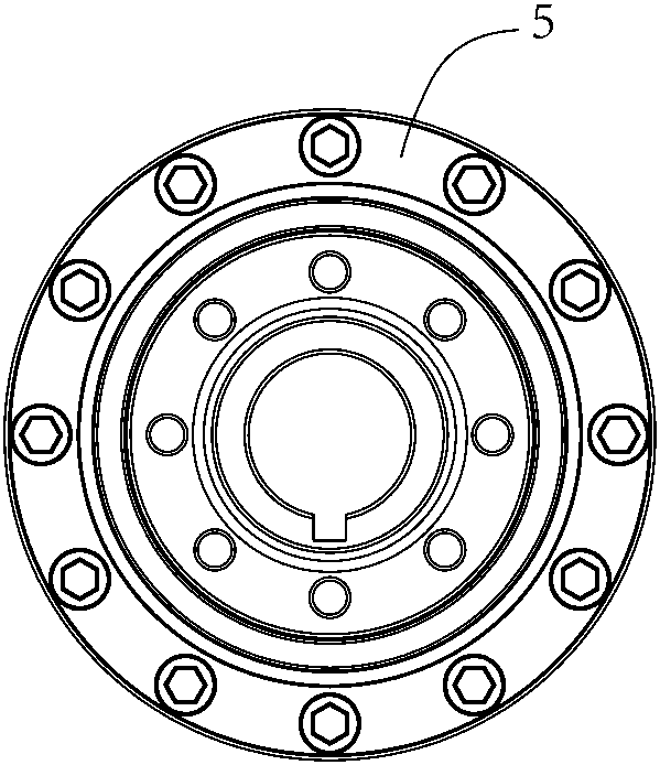
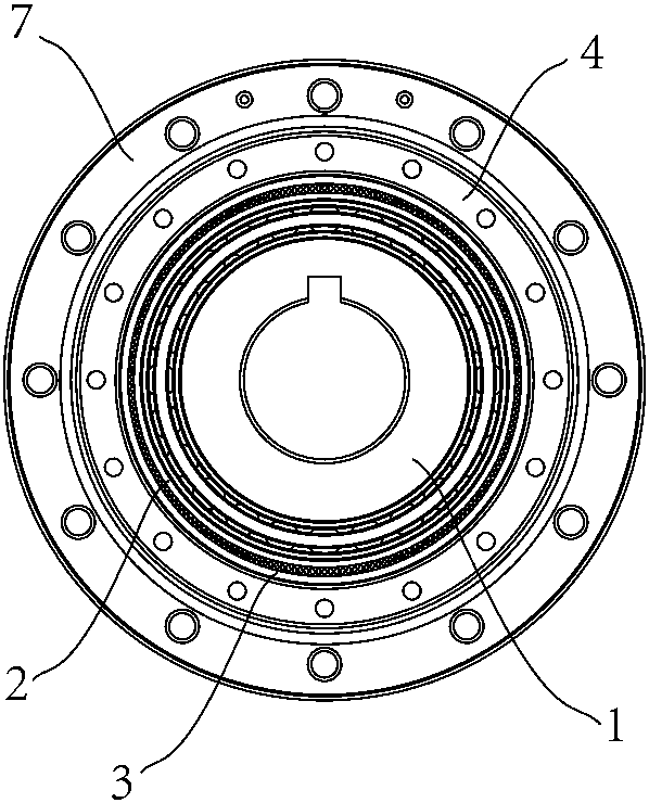
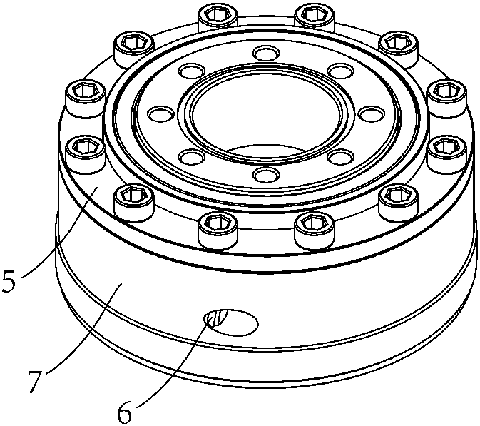
[0028] Embodiment 1: as Figure 1~6 As shown, the precision-compensated harmonic reducer consists of an outer flexspline, an inner flexspline, a wave generator, a deformation limiting part of the outer flexspline, an accuracy compensation adjusting worm, a shell component, and the main bearing of the reducer; the outer flexspline One end of the tubular wall of the wheel is connected and fixed with the outer shell, and the other end of the tubular wall of the outer flexspline is provided with 202 internal teeth. There are 200 external teeth meshing with the inner gear of the outer flexspline. Both the inner and outer flexsplines use trapezoidal teeth. The wave generator is an elliptical wave generator set inside the inner flexspline to cause elliptical elastic deformation of the inner flexspline. The position of the long axis of the ellipse is And it meshes with the internal teeth of the outer flexspline, and the contact part of the outer flexspline and the inner flexspline pro...


PUM


Abstract

The invention relates to a precision compensation type harmonic speed reducer. The precision compensation type harmonic speed reducer is characterized by comprising an outer flexible gear, an inner flexible gear, a wave generator, an outer flexible gear deformation limiting part, a precision compensation adjusting worm and a housing; and one end of a pipe-shaped wall of the outer flexible gear isfixedly connected with the housing, inner teeth are arranged on the other end of the pipe-shaped wall of the outer flexible gear, the inner flexible gear and the outer flexible gear are coaxially fixed axially and radially, outer teeth which can be engaged with an inner gear of the outer flexible gear are arranged on the inner flexible gear, the number of the teeth of the outer flexible gear is greater than that of the inner flexible gear, the wave generator is arranged in the inner flexible gear, so that non-circular elastic deformation of the inner flexible gear occurs, the wave generator ispartially engaged with the outer flexible gear, radial pressure of the inner flexible gear is applied to the contact part of the outer flexible gear and the inner flexible gear so as to generate non-circular elastic deformation, an annular beveled or arced limiting contact surface is arranged on the outer pipe wall of the back surface of the inner teeth of the flexible pipe-shaped wall of the outer flexible gear, and external threads and an outer helical gear are arranged on the outer flexible gear deformation limiting part.

Description

technical field [0001] The invention relates to the field of reducers, in particular to an accuracy compensation type harmonic reducer. Background technique [0002] Harmonic gear transmission was invented by American inventor C.W.Musser in 1955. It is a new type of transmission method that uses elastic deformation of flexible working components for motion or power transmission. It breaks through the rigid component mechanism of mechanical transmission. Mode, using a flexible component to achieve mechanical transmission, thus obtaining a series of special functions that other transmissions are difficult to achieve. Because the deformation process of the middle flexible member is basically a symmetrical harmonic, it gets its name. Except that the former Soviet Union called this kind of transmission wave transmission or flexible wheel transmission, the United States, Britain, Germany, Japan and other countries all call it "harmonic transmission". [0003] The traditional har...

Claims


Application Information

Patent Timeline
IPC IPC(8): F16H49/00
CPCF16H49/001
Inventor 凌子龙
Owner AICI TECH (NINGBO) CO LTD
Why Eureka
Try Eureka