
Linkage bank brake

A belt brake and linkage technology, applied in hydraulic drum brakes, brake actuators, gear shifting mechanisms, etc., can solve the problem of low emergency response and achieve good emergency response.

Active Publication Date: 2019-10-15
WUHAN MARINE MACHINERY PLANT
View PDF5 Cites 0 Cited by
  • Summary
  • Abstract
  • Description
  • Claims
  • Application Information

AI Technical Summary

Problems solved by technology

However, when actually controlling the band brake, manual drive and drive cylinder drive usually belong to two braking methods. In an emergency, it may take a certain amount of time to switch between the two braking methods. The control of the brake band is not very emergency.

Method used


Image

  • Linkage bank brake
  • Linkage bank brake
  • Linkage bank brake

Examples


Embodiment Construction

[0025] In order to make the object, technical solution and advantages of the present invention clearer, the embodiments of the present invention will be further described in detail below in conjunction with the accompanying drawings.

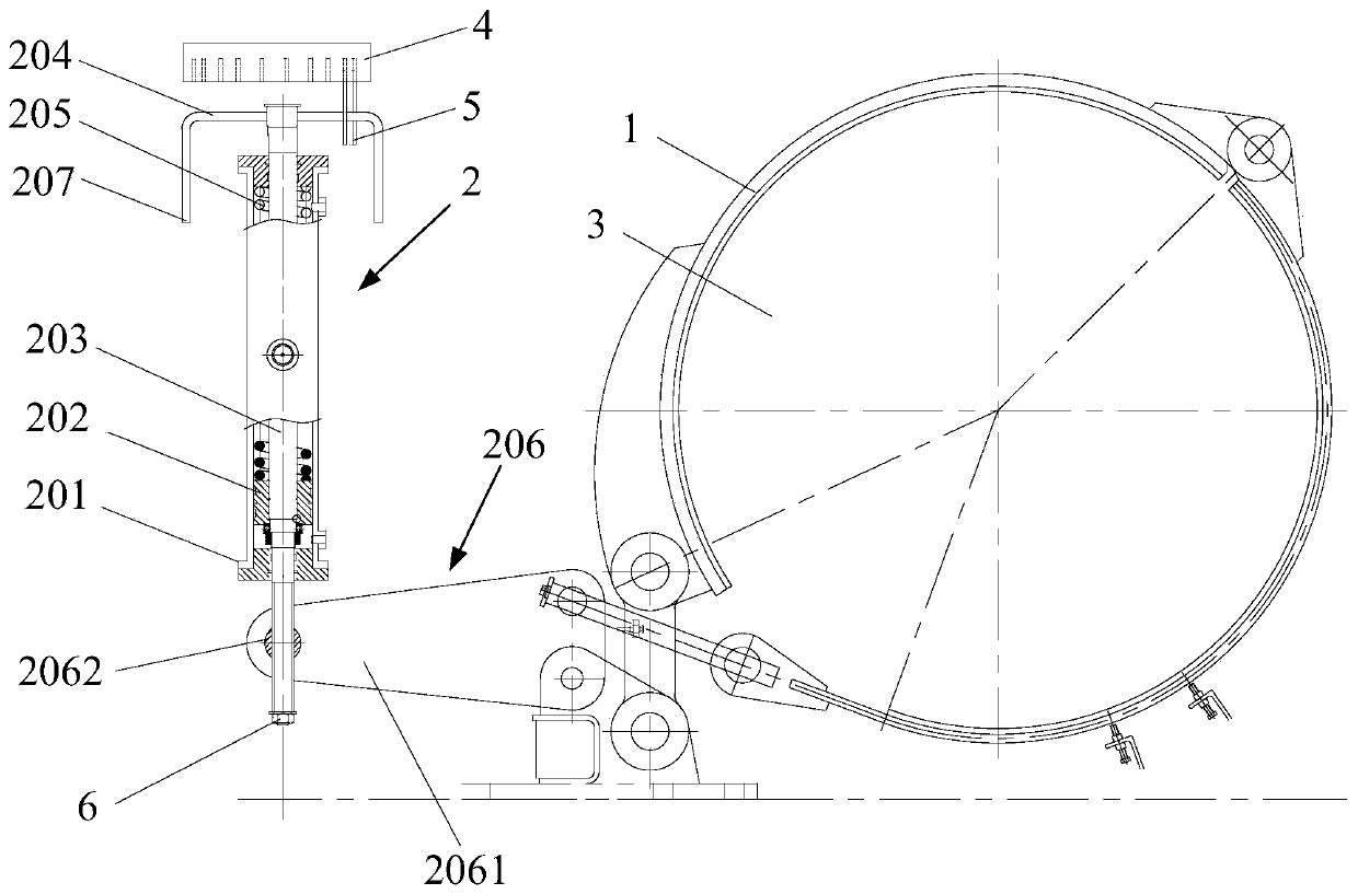
[0026] figure 1 It is a structural schematic diagram of a linked band brake provided by an embodiment of the present invention. Such as figure 1 As shown, the linkage type band brake includes a brake band 1 and a drive structure 2, the brake band 1 is used to wrap on the brake wheel 3, one end of the brake band 1 is fixed, and the other end of the brake band 1 is transmitted to the drive structure 2 connect.

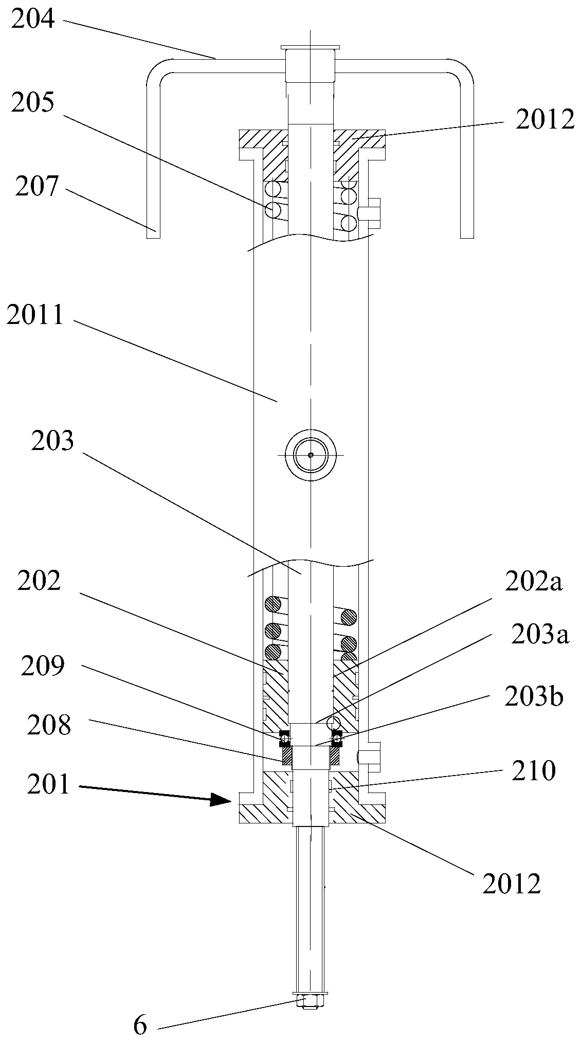
[0027] The driving structure 2 includes a cylinder housing 201 , a spring seat 202 , a driving rod 203 , a hand lever 204 , a spring 205 and a control member 206 .

[0028] The spring seat 202 is coaxially arranged in the oil cylinder housing 201, the spring seat 202 is sealed and connected with the oil cylinder housing 201, the driving...


PUM


Abstract

The invention discloses a linkage band brake, and belongs to the field of mechanical equipment. In actual use, hydraulic oil can be led into an oil cylinder shell on one side of a spring seat, and thespring seat is pushed through the hydraulic oil so that a driving rod is driven to move along the driving rod axially; a control panel is driven by the other end of the driving rod to move along thedriving rod axially, and the control panel is rotated by taking the fixed position of a control part as a fulcrum so that a brake band hinged with the control part is driven to release or brake a brake wheel; and finally the brake band is reset under the effect of springs located on the oil cylinder shell and one side of the spring seat. A manual lever can be further controlled to rotate for controlling the driving rod to rotate, and the driving rod and the oil cylinder shell are connected hermetically; and the driving rod is rotated so that the control part which is in threaded connected withthe driving rod is moved in the axial direction of the driving rod, and the brake wheel is braked or released. The linkage band brake is applied to the driving rod during control, and people do not need to take time for switching the manual and hydraulic control modes; and the emergency response is better.

Description

technical field [0001] The invention relates to the field of mechanical equipment, in particular to a linkage type band brake. Background technique [0002] Band brakes are common devices used to brake brake wheels. The conventional structure of a band brake includes a brake band for wrapping a brake wheel and an actuating cylinder. The brake belt is wrapped on the brake wheel, one end of the brake belt is fixed, the other end of the brake belt is connected with the piston rod of the driving cylinder, and the piston rod of the driving cylinder is stretched to control the closing and releasing of the brake belt to the brake wheel . [0003] For safety reasons, the band brake controlled by the drive cylinder generally also adds a manual drive at the other end of the brake band to control the closing and releasing of the brake band to the brake wheel. However, when actually controlling the band brake, manual drive and drive cylinder drive usually belong to two braking method...

Claims


Application Information

Patent Timeline
Patent Type & Authority Applications(China)
IPC IPC(8): F16D49/12F16D65/18F16D121/04
CPCF16D49/12F16D65/18F16D2121/04
Inventor 张彪明国军王恒智赵建虎
Owner WUHAN MARINE MACHINERY PLANT
Learn More