
Road surface maintenance device for road and bridge construction

A bridge construction and road technology, applied in soil protection, infrastructure engineering, construction, etc., can solve the problems of increasing workload and labor force, increasing labor force of construction team, and heavy weight of vibration compactor, and reducing labor force and workload. , the effect of reducing labor and increasing firmness

Active Publication Date: 2021-02-26
中铁城乡环保工程有限公司 +1
View PDF1 Cites 0 Cited by
  • Summary
  • Abstract
  • Description
  • Claims
  • Application Information

AI Technical Summary

Problems solved by technology

[0003] The existing widely used ground compaction tools are generally vibratory compactors, which are mainly composed of a vibrator system, a tamping plate, and a spring system. Ramping machine" forms high-frequency vibration through the vibrating machine system, so that the ramming plate vibrates at high frequency on the ground through the spring system, continuously and quickly hits the ground, and causes the resonance of the ground to increase the compactness of the ground, but this type of tamping The machine can only be used on the soft road surface that has just been constructed, and there are hollows or gaps in the ground that has been compacted because the surrounding soil has been beaten and squeezed into a very compact state, so the use of this type of vibratory compactor cannot be effective. To eliminate the gaps and hollows under the foundation, it is only possible to excavate this area and compact it again, which will increase the workload and labor force, and the existing vibratory compaction machine is relatively difficult to haul and move due to its heavy weight, which increases construction team workforce

Method used


Image

  • Road surface maintenance device for road and bridge construction
  • Road surface maintenance device for road and bridge construction
  • Road surface maintenance device for road and bridge construction

Examples


Embodiment Construction

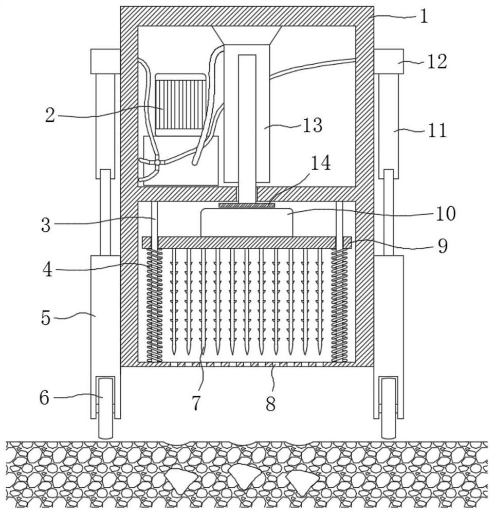
[0022] The following will clearly and completely describe the technical solutions in the embodiments of the present invention with reference to the accompanying drawings in the embodiments of the present invention. Obviously, the described embodiments are only some, not all, embodiments of the present invention.

[0023] In describing the present invention, it should be understood that the terms "upper", "lower", "front", "rear", "left", "right", "top", "bottom", "inner", " The orientation or positional relationship indicated by "outside", etc. is based on the orientation or positional relationship shown in the drawings, and is only for the convenience of describing the present invention and simplifying the description, rather than indicating or implying that the referred device or element must have a specific orientation, so as to Specific orientation configurations and operations, therefore, are not to be construed as limitations on the invention.

[0024] refer to Figure ...


PUM


Abstract

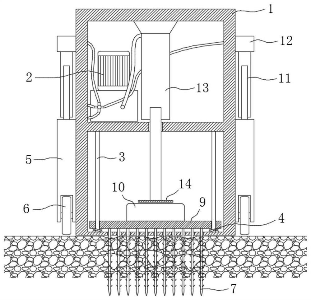
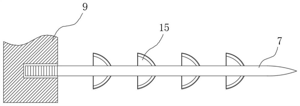
The invention discloses a road surface maintenance device for road and bridge construction, which comprises a machine body, which is divided into a hydraulic chamber and a tamping chamber from top to bottom, and four hydraulic moving mechanisms are symmetrically installed on the side wall of the body. The inner bottom wall and the inner top wall of the tamping chamber are symmetrically and fixedly installed with a plurality of positioning columns, and a tamping plate is slidably installed on the plurality of positioning columns, and a return spring is installed on each of the positioning columns, and the return spring The upper end and the lower end are respectively fixed on the lower bottom surface of the tamping plate and the lower bottom wall of the tamping chamber. The invention uses a hydraulic moving mechanism to make the machine body more convenient to move and work at the construction site, and can easily move to any construction area, reducing labor force. The conical thorns and arc-shaped deflectors penetrate into the foundation to vibrate, so that the gaps in the foundation and The hollow layer is filled tightly by the surrounding vibrating and soft soil layer, which increases the firmness of the foundation, and there is no need to re-excavate the foundation for filling, reducing the labor and workload of the construction team.

Description

technical field [0001] The invention relates to the field of road construction, in particular to a road surface maintenance device for road and bridge construction. Background technique [0002] During the construction of roads and bridges, the compaction of the ground foundation is particularly important. If there are voids or hollow areas in the ground foundation, it will cause the road surface to collapse or the bridge to collapse when the road and bridge are constructed and used, and then lead to a series of safety accidents, with extremely high consequences. Serious, so the construction team needs to repeatedly inspect the foundation compaction work and carry out supplementary compaction work to increase the firmness of the foundation. [0003] The existing widely used ground compaction tools are generally vibratory compactors, which are mainly composed of a vibrator system, a tamping plate, and a spring system. Ramping machine" forms high-frequency vibration through t...

Claims


Application Information

Patent Timeline
Patent Type & Authority Patents(China)
IPC IPC(8): E02D3/046E02D3/054
CPCE02D3/046E02D3/054
Inventor 张德明
Owner 中铁城乡环保工程有限公司
Learn More