
Counterweight frame with gravity center adjustable

A counterweight frame, adjustable technology, applied in the field of counterweight frame, can solve the problem of affecting the installation, affecting the comfort of elevator operation, inconvenience, etc., to achieve the effect of stable operation and convenient weight distribution

Pending Publication Date: 2019-10-15
ZHEJIANG MEILUN ELEVATOR
View PDF0 Cites 2 Cited by
  • Summary
  • Abstract
  • Description
  • Claims
  • Application Information

AI Technical Summary

Problems solved by technology

[0002] The speed of the elevator generally increases with the increase of the total height of the building. When the building is very high, the weight change of the wire rope of the elevator traction system cannot be ignored, which will affect the balance of the system and thus affect the comfort of the elevator. Generally, compensation Chains or compensation wire ropes are used to balance the quality of the system, and generally compensation chains or compensation wire ropes are installed at the center of gravity of the counterweight system (usually at the bottom center of the counterweight system), which will affect the buffer at the bottom of the counterweight frame or have The installation of devices such as counterweight safety gear, but the weight balance adjustment process of the existing elevator counterweight frame is inconvenient

Method used


Image

  • Counterweight frame with gravity center adjustable
  • Counterweight frame with gravity center adjustable
  • Counterweight frame with gravity center adjustable

Examples


Embodiment Construction

[0015] The following will clearly and completely describe the technical solutions in the embodiments of the present invention with reference to the accompanying drawings in the embodiments of the present invention. Obviously, the described embodiments are only some, not all, embodiments of the present invention. Based on the embodiments of the present invention, all other embodiments obtained by persons of ordinary skill in the art without making creative efforts belong to the protection scope of the present invention.

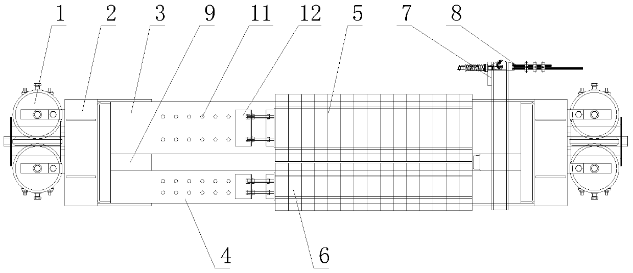
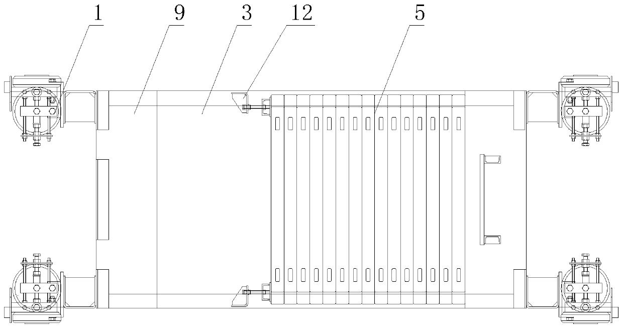
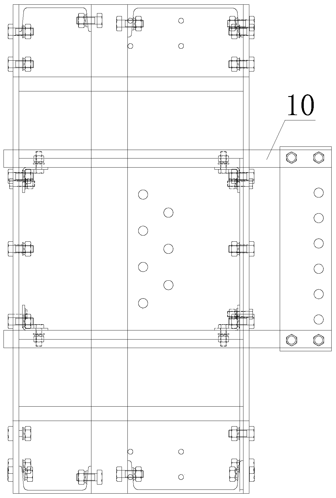
[0016] see Figure 1-3 , a counterweight frame with an adjustable center of gravity, including a guide shoe 1, a guide shoe adapter 2, a first counterweight frame 3, a second counterweight frame 4, a counterweight frame connector 9 and a compensation rope end support 10 , the guide shoe 1 is set at the four corners of the whole device, so that the overall force is balanced and the stability is good. The guide shoe 1 is fixedly connected to the guide shoe adapt...


PUM


Abstract

The invention discloses a counterweight frame with a gravity center adjustable. The counterweight frame comprises a guide shoe, a guide shoe rotating connection seat, a first counterweight frame, a second counterweight frame, counterweight frame connecting pieces and a compensation rope head supporting piece, wherein the guide shoe is fixedly connected with the guide shoe rotating connection seatthrough a support, the inner wall of the guide shoe rotating connection seat is fixedly connected with the counterweight frame connecting pieces, and the counterweight frame connecting pieces are arranged at the two ends of the first counterweight frame and the second counterweight frame. According to the counterweight frame with the gravity center adjustable, long holes which are regularly distributed are formed in the side walls of the two counterweight frames, counterweight block fastening devices are connected with the long holes through locking screws, the weight of counterweight blocks which are connected with the counterweight block fastening devices can be controlled by installing the counterweight block fastening devices at the long holes at different positions, so that the overall weight distribution can be conveniently adjusted; and meanwhile, the compensation rope head supporting piece is connected with the first counterweight frame and the second counterweight frame through bolts, the position of the compensation rope head supporting piece can be adjusted, so that the overall weight balance is further controlled, and the operation of the elevator is stable.

Description

technical field [0001] The invention relates to the technical field, in particular to a counterweight frame with an adjustable center of gravity. Background technique [0002] The speed of the elevator generally increases with the increase of the total height of the building. When the building is very high, the weight change of the wire rope of the elevator traction system cannot be ignored, which will affect the balance of the system and thus affect the comfort of the elevator. Generally, compensation Chains or compensation wire ropes are used to balance the quality of the system, and generally compensation chains or compensation wire ropes are installed at the center of gravity of the counterweight system (usually at the bottom center of the counterweight system), which will affect the buffer at the bottom of the counterweight frame or have The installation of devices such as counterweight safety gear, but the weight balance adjustment process of the existing elevator coun...

Claims


Application Information

Patent Timeline
Patent Type & Authority Applications(China)
IPC IPC(8): B66B17/12B66B11/04B66B7/04
CPCB66B17/12B66B11/04B66B7/04
Inventor 於刚毅沈福韩伟良杨涛罗建林杨晨曦赵晓杰赵作栋朱虹钱利清谈金林
Owner ZHEJIANG MEILUN ELEVATOR
Learn More