This helps you quickly interpret patents by identifying the three key elements:
Problems solved by technology
Method used
Benefits of technology
Problems solved by technology
However, gradient coils are usually not used with the same duty cycle and most of the cooling system's capacity is wasted
Method used
Image
Click on the blue label to locate the original text in one second.
Reading with bidirectional positioning of images and text.
Examples
Embodiment Construction
[0074] In the following, like-numbered elements in the figures are either similar elements or perform equivalent functions. Elements that have been discussed previously will not necessarily be discussed in a later figure if the function is equivalent.
[0075] Various structures, systems and devices are schematically depicted in the drawings for purposes of explanation only and so as not to obscure the present invention with details that are well known to those skilled in the art. Nevertheless, the accompanying drawings are included to describe and explain illustrative examples of the disclosed subject matter.
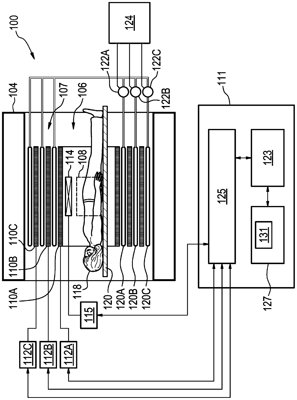
[0076] figure 1 A magnetic resonance imaging system 100 is illustrated as an example of a medical system 100 . The magnetic resonance imaging system 100 includes a magnet 104 . The magnet 104 is a superconducting cylindrical magnet having a bore 106 therein. It is also possible to use different types of magnets; for example split cylindrical magnets and so-called o...
PUM
Abstract
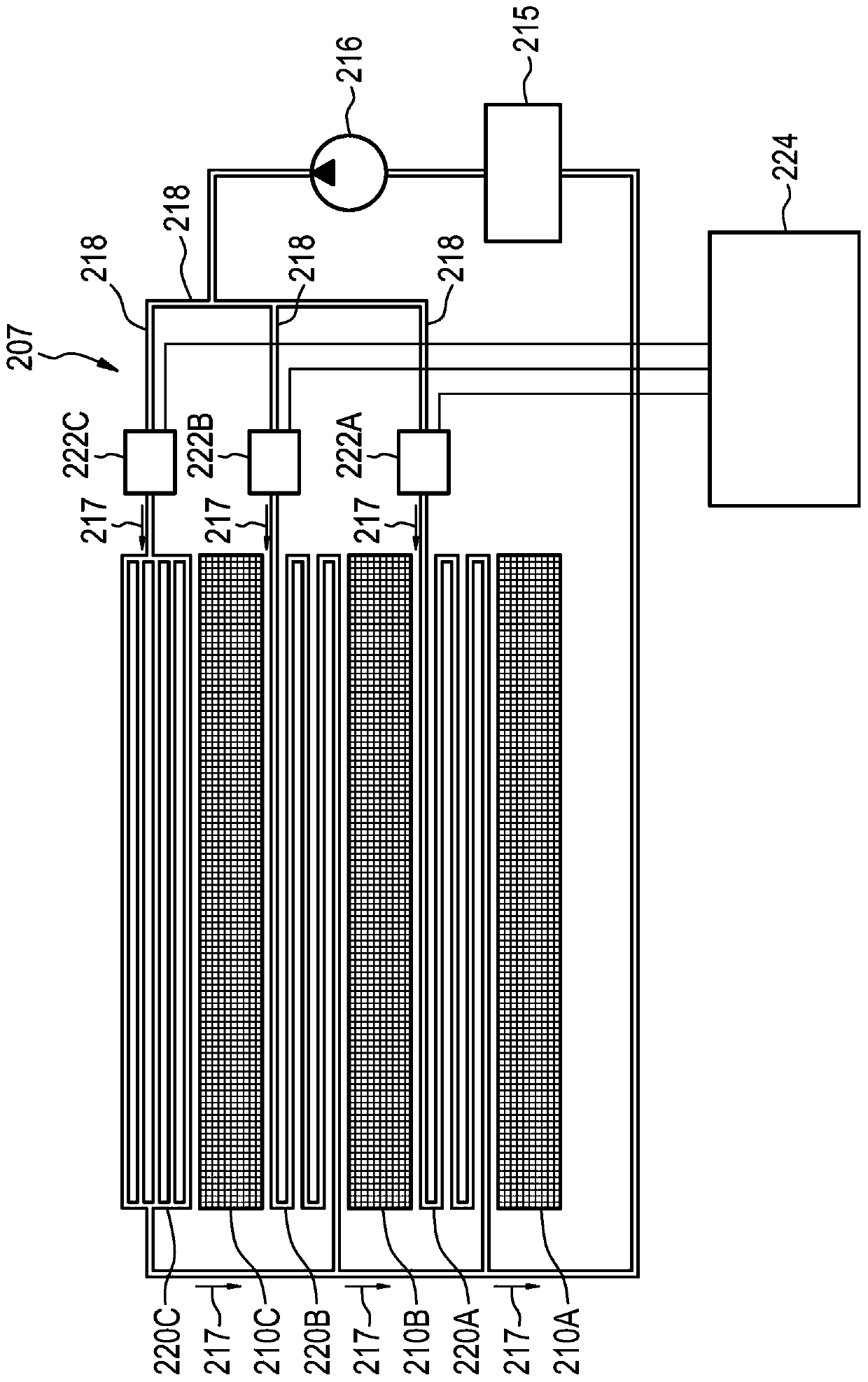
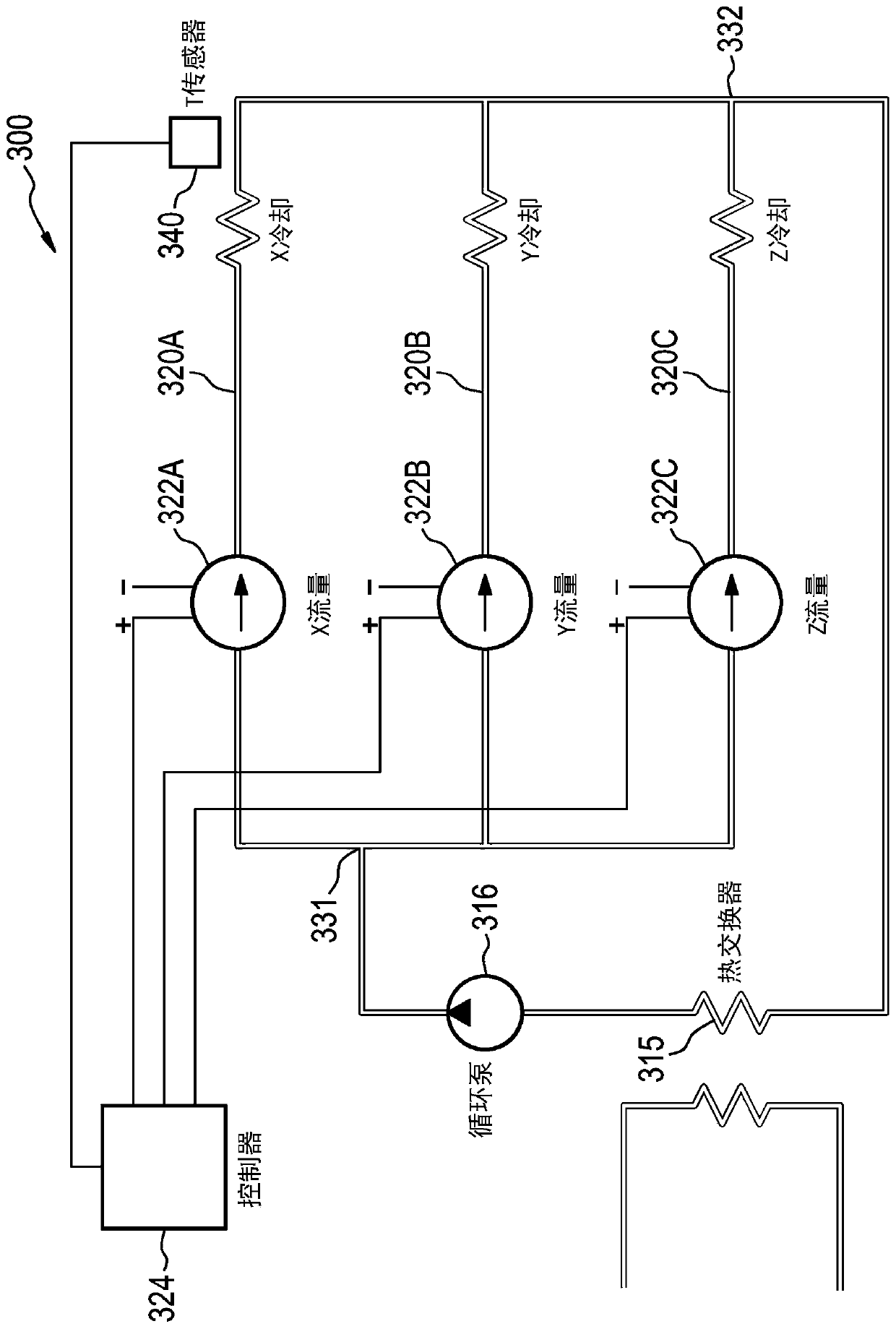
The present disclosure relates to a gradient coil system (107, 207) for a magnetic resonance imaging, MRI, system (100). The gradient coil system (107, 207) comprises: a plurality of gradient coils (110A-C, 210A-C) for applying a gradient magnetic field to a target volume (108); at least one coolant tube (120A-C, 220A-C, 320A-C) per gradient coil (110A-C, 210A-C) for cooling the gradient coil (110A-C, 210A-C), the coolant tubes (120A-C, 220A-C, 320A-C) being connected to respective flow control devices (122A-C, 222A-C, 322A-C); a controller (124, 224, 324) coupled to the coolant tubes (120A-C,220A-C, 320A-C) configured to control each flow control device of the flow control devices (122A-C, 222A-C, 322A-C) for adjusting the flow of a coolant in the respective coolant tube (120A-C, 220A-C,320A-C), wherein the controller (124, 224, 324) is configured to control the flow control device (122A-C, 222A-C, 322A-C) on the basis of heat load caused by the respective gradient coil (110A-C, 210A-C).
Description
technical field [0001] The present invention relates to scanning imaging systems, in particular to cooling systems for gradient coil devices. Background technique [0002] Chillers utilizing water or a water and glycol mixture are commonly used to remove heat from the gradient coils of a magnetic resonance (MR) system. To minimize flow resistance, the cooling system consists of many parallel lines served by chillers. However, the gradient coils are usually not used with the same duty cycle and most of the cooling system's capacity is wasted. [0003] Japanese patent application JP H06-54819 relates to an open type magnet with opposing pole pieces of permanent magnets. The gradient coils are mounted on the corresponding pole heads. The gradient coils are liquid-cooled, and the cooling of the same pole head for the x gradient coils is piped in series with the cooling of the y gradient coils. The cooling of the gradient (x,y) coils at different pole tips is controlled separ...
Claims
Application Information
Patent Timeline
Application Date:The date an application was filed.
Publication Date:The date a patent or application was officially published.
First Publication Date:The earliest publication date of a patent with the same application number.
Issue Date:Publication date of the patent grant document.
PCT Entry Date:The Entry date of PCT National Phase.
Estimated Expiry Date:The statutory expiry date of a patent right according to the Patent Law, and it is the longest term of protection that the patent right can achieve without the termination of the patent right due to other reasons(Term extension factor has been taken into account ).
Invalid Date:Actual expiry date is based on effective date or publication date of legal transaction data of invalid patent.