Return light resistant all-fiber device

A return light, all-fiber technology, applied in laser parts, lasers, electrical components, etc., can solve problems such as increasing heat generation, destroying resonators, and damaging optical fiber devices, achieving industrialization, easy integration, and efficient stripping. Effect

Active Publication Date: 2019-10-11
JIANGSU HENGTONG OPTICAL FIBER TECH +1
View PDF19 Cites 1 Cited by
  • Summary
  • Abstract
  • Description
  • Claims
  • Application Information

AI Technical Summary

Problems solved by technology

At present, the commonly used method is to use the cladding optical filter to strip the return light, but when the cladding optical filter strips the cladding light laser and the remaining pump light of the high-power output laser, the optical power of hundreds of watts is stripped. , the device itself will generate a certain amount of heat. If there is high-power return light entering the cladding optical filter at this time, it will increase the load on the device and increase the heat generation. The heat generation of the device will affect the filtering performance, and there will be return light Entering the resonator will affect the stability of the laser operation, and in severe cases, the cladding optical filter will be burned
In addition, if there is a Stokes light component in the returned light, it will be amplified by power during reverse transmission. This kind of light reverse transmission is extremely harmful, and it will damage the optical fiber device and destroy the resonant cavity during the return process.

Method used


Image

  • Return light resistant all-fiber device
  • Return light resistant all-fiber device
  • Return light resistant all-fiber device

Examples


Embodiment

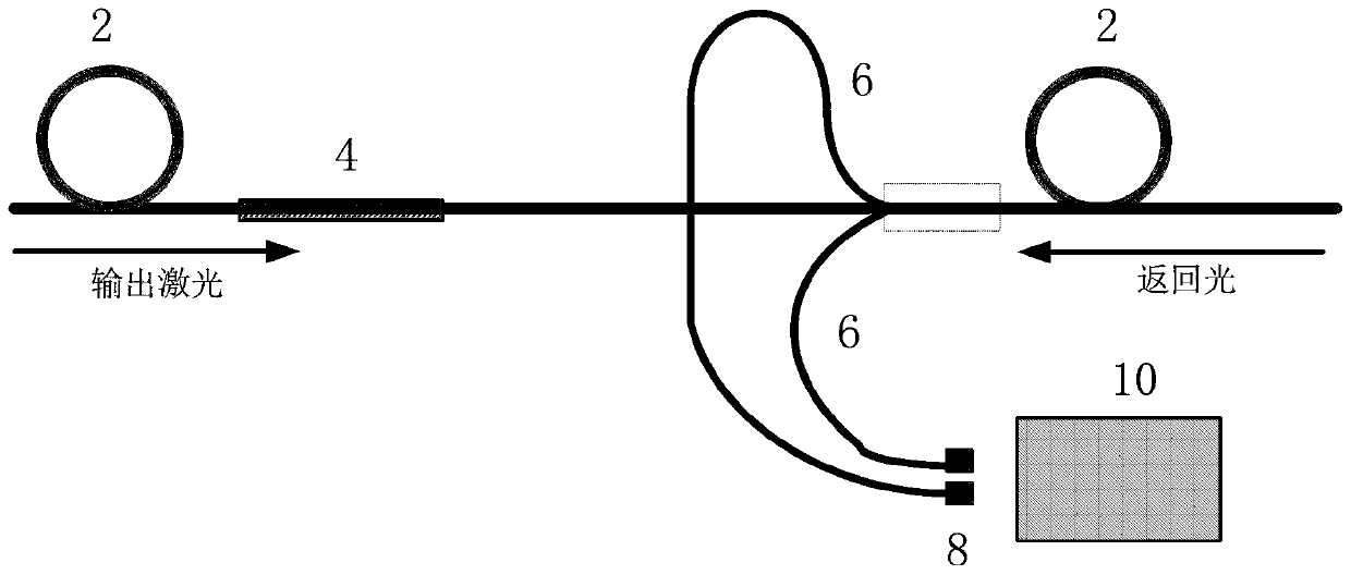
[0029] refer to figure 1 As shown, this embodiment discloses an anti-return light all-fiber device, including an energy transmission fiber 2, a cladding light filter 4, and a beam splitting fiber 6. Along the output laser direction of the energy transmission fiber 2, the above cladding light The filter 4 and the splitting optical fiber 6 are arranged in sequence.

[0030] The above-mentioned energy transmission fiber 2 is used in high-power fiber laser equipment, preferably a double-clad fiber or a triple-clad fiber. Energy confinement is transmitted in the core of the energy-transmitting optical fiber 2 . Commonly used double-clad models are 20 / 400μm, 20 / 250μm, 25 / 250μm, 25 / 400μm, 30 / 250μm, 30 / 400μm, 30 / 600μm, 50 / 360μm, 50 / 400μm, 100 / 330μm, 100 / 360μm , 400 / 480μm and other specifications and models. Commonly used three-clad models include 50 / 70 / 360μm, 50 / 70 / 480μm, 100 / 120 / 360μm, 100 / 130 / 660μm and other specifications.

[0031] The splitting fiber 6 is coupled to the claddi...


PUM

PropertyMeasurementUnit
Core diameteraaaaaaaaaa

Abstract

The invention discloses a return light resistant all-fiber device, comprising an energy transfer fiber, a cladding light filter and beam splitting fibers. The cladding light filter is prepared on theenergy transfer fiber. The beam splitting fibers are coupled on a cladding of the energy transfer fiber. The cladding light filter and the beam splitting fibers are set in sequence along a laser output direction of the energy transfer fiber. The beam splitting fibers are used for exporting return light which is applied to a target object by the energy transfer fiber and is reflected by the targetobject. The cladding light filter is used for filtering the return light through destruction of a light beam total emission condition of the cladding of the energy transfer fiber. The beam splitting fibers and the cladding light filter are imported into the energy transfer fiber for outputting laser, most of return light power is exported through utilization of the beam splitting fibers, further the return light is stripped through combination of the cladding light filter, and the cladding light filter further effectively filters the return light which is not exported, so the fiber device provided by the invention has high power return light resistance.

Description

technical field [0001] The invention belongs to the field of optical fiber laser technology, and in particular relates to an anti-return light all-fiber device. Background technique [0002] In the cutting and welding applications of high-power fiber laser equipment, especially in the processing of highly reflective materials such as copper, aluminum and their alloys, return light processing has always been one of the technical problems in the field of high-power fiber laser applications. When materials with high reflection coefficients such as copper, aluminum and their alloys are on the surface of the material with the laser beam, a part of the laser light will propagate along the original optical fiber path and return. This return light will cause the laser to run unstable, and cause the laser protection device to alarm and Stopping work and running for a long time will shorten the life of the laser, and in serious cases will destroy the fiber laser. Insufficient anti-hi...

Claims


Application Information

Patent Timeline
IPC IPC(8): H01S3/067
CPCH01S3/06708H01S3/06733
Inventor 孙伟姚之圃朱永刚郭洁阎权潘超宋君严勇虎陈伟
Owner JIANGSU HENGTONG OPTICAL FIBER TECH
Why Eureka
Try Eureka