
Compressor fan and compressor

A compressor and fan technology, which is applied in the field of compressors, can solve the problems of high aerodynamic noise of fans, etc., achieve the effects of reducing aerodynamic injection noise, reducing gas speed, and solving large aerodynamic noise

Pending Publication Date: 2019-10-11
ZHUHAI LANDA COMPRESSOR +1
View PDF0 Cites 0 Cited by
  • Summary
  • Abstract
  • Description
  • Claims
  • Application Information

AI Technical Summary

Problems solved by technology

[0003] The purpose of the present invention is to provide a compressor fan and compressor to solve the problem of relatively large aerodynamic noise generated by the fan in the prior art

Method used


Image

  • Compressor fan and compressor
  • Compressor fan and compressor
  • Compressor fan and compressor

Examples


Embodiment Construction

[0030] In order to make the purpose, technical solution and advantages of the present invention clearer, the technical solution of the present invention will be described in detail below. Apparently, the described embodiments are only some of the embodiments of the present invention, but not all of them. Based on the embodiments of the present invention, all other implementations obtained by persons of ordinary skill in the art without making creative efforts fall within the protection scope of the present invention.

[0031] This specific embodiment provides a compressor fan and a compressor, which solve the problem of relatively large aerodynamic noise generated by the fan in the prior art.

[0032] Hereinafter, the embodiments will be described in detail in conjunction with the accompanying drawings. In addition, the examples shown below do not limit the content of the invention described in the claims in any way. In addition, all the contents of the configurations shown ...


PUM

PropertyMeasurementUnit
Diameteraaaaaaaaaa

Abstract

The invention discloses a compressor fan and a compressor. The compressor fan comprises a substrate and a plurality of blades, wherein the blades are connected with the substrate and are arranged along a radial direction of the substrate; each blade is provided with a through hole penetrated along a width direction of the blade. Through the arrangement, a gas channel is formed between two blades;each blade is provided with the through hole, so that two adjacent gas channels communicate with each other; meanwhile, non-channel area located at the outer sided of the blades at the edge communicate with the gas channels, so that the gas is leaked when the fan operates, the gas pressure is reduced, the gas injection speed is reduced, and the pneumatic injection noise is reduced; and the problemof high pneumatic noise generated by the fan in the prior art is solved.

Description

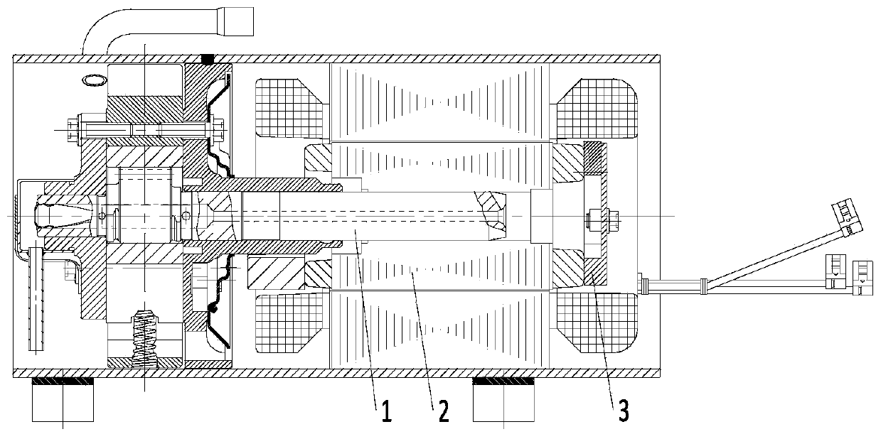
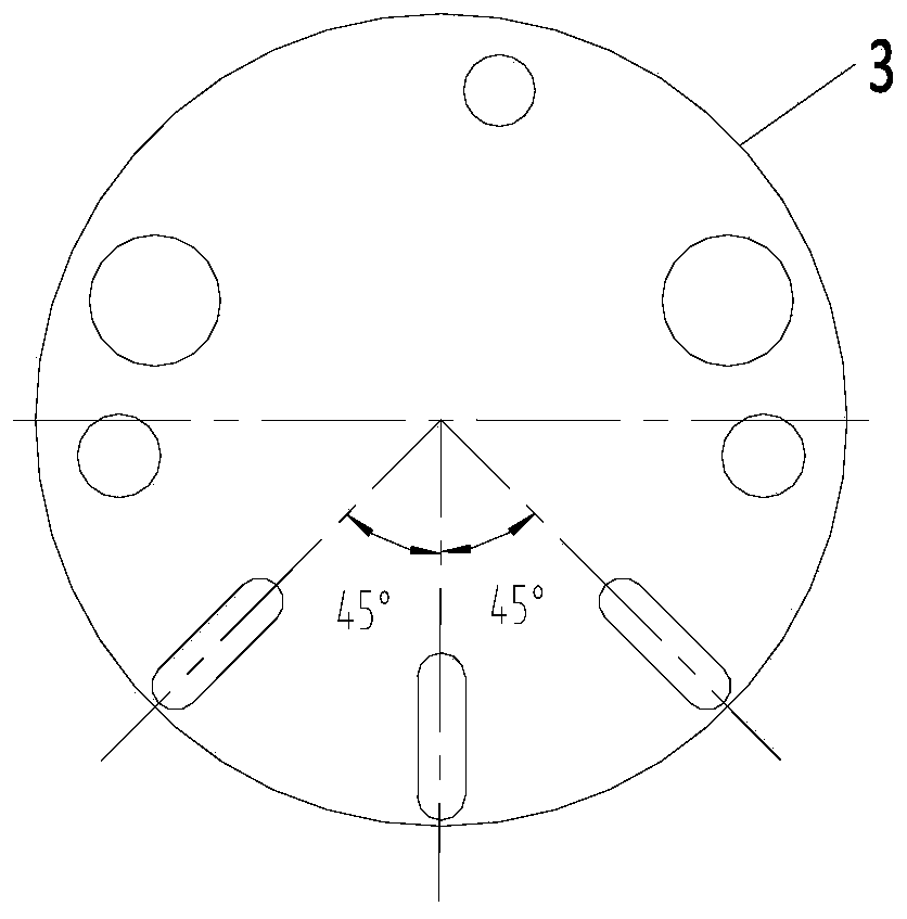
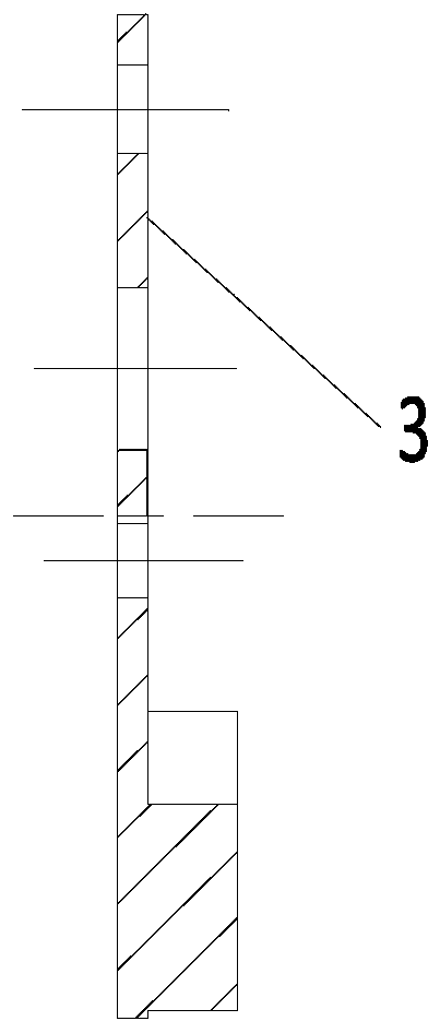
technical field [0001] The present invention relates to the technical field of compressors, more specifically, to a compressor fan and a compressor. Background technique [0002] For the existing horizontal compressors, in order to ensure the oil supply of the shafting, such as figure 1 As shown, a part called fan 3 is often fixedly installed on the rotor 2 of the crankshaft 1 long axis section. Such as figure 2 As shown, the fan 3 is usually provided with three radially arranged blades, and a gas channel is formed between two adjacent blades. When the fan 3 rotates with the rotor 2 at high speed, the blade draws air from the inside to the outside through two gas passages to reduce the gas pressure in the center of the rotor 2, thus ensuring the oil supply to the shafting of the horizontal compressor. However, the existing fan 3 is in the high-pressure refrigerant gas. When the fan 3 rotates at a high speed, its blades will inevitably stir the high-pressure refrigerant. ...

Claims


Application Information

Patent Timeline
IPC IPC(8): F04C29/02F04D29/28F04D29/30F04D29/66
CPCF04C29/02F04D29/282F04D29/30F04D29/663F04D29/666
Inventor 李玉斌
Owner ZHUHAI LANDA COMPRESSOR
Learn More