Control method for expanding operating range of cascaded H-bridge photovoltaic inverter

A photovoltaic inverter and control method technology, applied in photovoltaic power generation, single-network parallel feeding arrangement, AC network to reduce harmonics/ripples, etc., can solve large capacitor voltage fluctuations, reduce system power generation, and cannot Meet grid-connected standards and other issues, achieve the effect of reducing the third harmonic component and the fluctuation of capacitor voltage is not large

Active Publication Date: 2019-10-08
HEFEI UNIV OF TECH
View PDF4 Cites 6 Cited by
  • Summary
  • Abstract
  • Description
  • Claims
  • Application Information

AI Technical Summary

Problems solved by technology

[0008] 1) When the output power of each H-bridge module is seriously unbalanced, although the reactive power compensation control strategy can ensure that all H-bridge modules are not modulated, the system power factor is low and cannot meet the grid-connected standard
[0009] 2) Although the hybrid modulation strategy can expand the operating range of the system to a certain extent, the DC side capacitor voltage fluctuates greatly, which will reduce the power generation of the system
[0010] 3) Although the third harmonic compensation strategy can make the system operate at unity power factor and the DC side capacitor voltage fluctuation is small, the compensation for the reverse third harmonic is open-loop compensation, which cannot guarantee that the grid current does not contain third harmonic components
Also, the distribution of the inverted third harmonic among non-overmodulated modules has not been addressed

Method used


Image

  • Control method for expanding operating range of cascaded H-bridge photovoltaic inverter
  • Control method for expanding operating range of cascaded H-bridge photovoltaic inverter
  • Control method for expanding operating range of cascaded H-bridge photovoltaic inverter

Examples


Embodiment Construction

[0053] In order to make the objectives, technical solutions and advantages of the present invention more clear, the present invention will be further clearly and completely described below in conjunction with the accompanying drawings and embodiments.

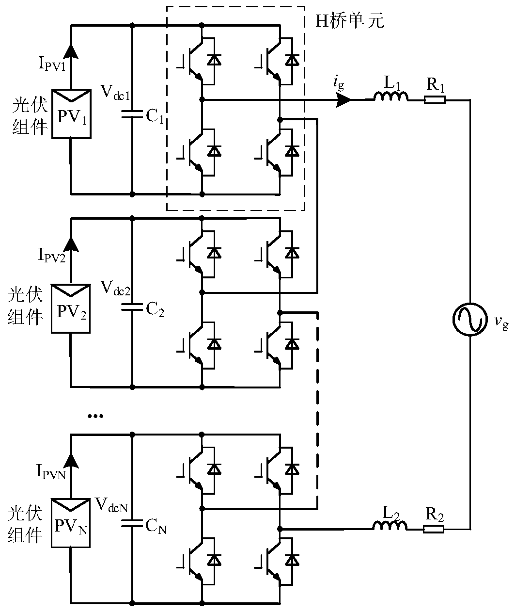
[0054] figure 1 The main circuit topology of the single-phase cascaded H-bridge photovoltaic grid-connected inverter implemented for the present invention includes N identical H-bridge units, and each H-bridge unit is composed of four fully-controlled switching devices. Each H-bridge front end is connected in parallel with an electrolytic capacitor C i , i=1,2,...,N, each electrolytic capacitor is connected with a photovoltaic cell PV i Connect, i=1,2,...,N. After the AC side outputs of all H-bridges are connected in series, the filter inductor L 1 and L 2 connected to the grid, where R 1 and R 2 Respectively filter inductance L 1 and L 2 equivalent resistance. V in the figure dci and I PVi Respectively represent the...


PUM


Abstract

The invention discloses a control method for expanding an operating range of a cascaded H-bridge photovoltaic inverter and belongs to the field of photovoltaic power generation. The method mainly comprises steps that (1), DC side voltages of all H-bridge units are controlled, and an active current command is obtained; (2), fundamental waves of the grid current are controlled, third harmonic wavesof the grid current are controlled, and an inverse third harmonic wave voltage required for compensation is obtained; (3), the degree of modulation of the H-bridge units is calculated, the third harmonic waves are compensated for the modulated H-bridge units, and modulated waves of the modulated H-bridge units are obtained; and (4), according to the proposed control method, the inverse third harmonic voltage is distributed to the non-overmodulated H-bridge units, and modulated waves of the non-overmodulated H-bridge units are obtained. The method is advantaged in that compared with published literatures in the prior art, the method can guarantee that a unit power factor of the inverter normally operates, DC-side capacitor voltage fluctuation is small and the third harmonic wave content ofthe grid current is relatively low when the input power is seriously unbalanced in the cascaded H-bridge photovoltaic grid-connected inverter.

Description

technical field [0001] The invention belongs to the photovoltaic power generation technology in the field of electrical engineering, and in particular relates to a control method for expanding the operating range of a single-phase cascaded H-bridge photovoltaic inverter. Background technique [0002] Compared with the traditional inverter, the cascaded H-bridge multilevel inverter has the advantages of low harmonic content of grid current, low switching frequency, small filter size and easy modularization, etc., so it has attracted the attention of many scholars. . In addition, the DC side of each H-bridge unit of the cascaded H-bridge multi-level inverter can be independently powered by a photovoltaic cell, making its independent maximum power point tracking (MPPT—Maximum Power Point Tracking) control possible, so the level The H-bridge multilevel topology is especially suitable for photovoltaic grid-connected inverters. [0003] Although each H-bridge unit of the cascade...

Claims


Application Information

Patent Timeline
IPC IPC(8): H02J3/38H02J3/18H02J3/01
CPCH02J3/385H02J3/01H02J3/1857Y02E10/56Y02E40/20Y02E40/30Y02E40/40
Inventor 张兴赵涛王明达毛旺刘芳王付胜
Owner HEFEI UNIV OF TECH
Why Eureka
Try Eureka