
Magnetic sensor array based rotation-movement magnetic anomaly target detection device and method

A magnetic sensor and rotary motion technology, applied in the field of rotary motion magnetic anomaly target detection devices, can solve the problems of lack of characteristic information of magnetic anomaly signals and low positioning accuracy, so as to facilitate transportation and transfer, accurate positioning results, and meet real-time detection The effect of positioning

Active Publication Date: 2019-10-08
NANJING UNIV OF SCI & TECH
View PDF18 Cites 14 Cited by
  • Summary
  • Abstract
  • Description
  • Claims
  • Application Information

AI Technical Summary

Problems solved by technology

[0004] The purpose of the present invention is to provide a vehicle-mounted rotary motion magnetic anomaly target detection device, which solves the lack of magnetic anomaly signal characteristic information, low positioning accuracy, and the problem of the linear motion of the platform using the STAR algorithm for single point positioning. dependencies etc.

Method used


Image

  • Magnetic sensor array based rotation-movement magnetic anomaly target detection device and method
  • Magnetic sensor array based rotation-movement magnetic anomaly target detection device and method
  • Magnetic sensor array based rotation-movement magnetic anomaly target detection device and method

Examples


Embodiment 1

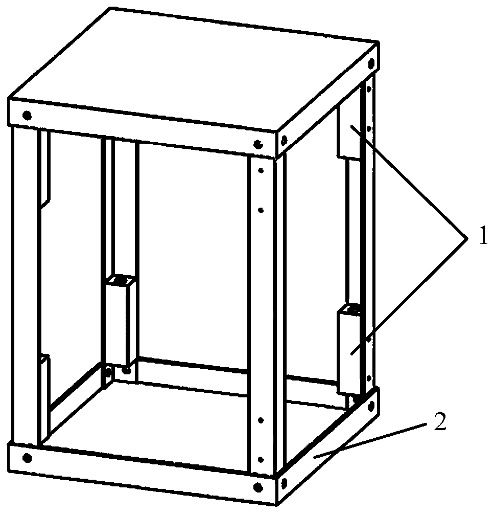
[0066] Such as figure 1 As shown, the magnetic sensor array is composed of 8 three-axis fluxgate sensors 1 and a magnetic sensor cube frame 2; the magnetic sensors 1 are located at the 8 vertices of the magnetic sensor cube frame 2, and the distance between adjacent magnetic sensors 1 is 0.3m; 8 magnetic sensors 1 are calibrated before installation, so their output performance can be regarded as basically consistent; the magnetic sensor cube frame 2 is made of non-magnetic materials such as aluminum alloy or carbon fiber.

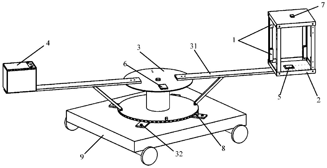
[0067] Such as figure 2 As shown, the magnetic sensor cube frame 2 is fixed on the long rod 31 on the rotating mechanism, so that the magnetic sensor array can do circular motion with the rotation of the rotating mechanism 3; in order to ensure that the magnetic sensor array can move in the horizontal plane, the rotating mechanism The bottom of 3 is equipped with adjusting screw 32, makes the rotation axis of rotating mechanism 3 perpendicular to horizont...

Embodiment 2

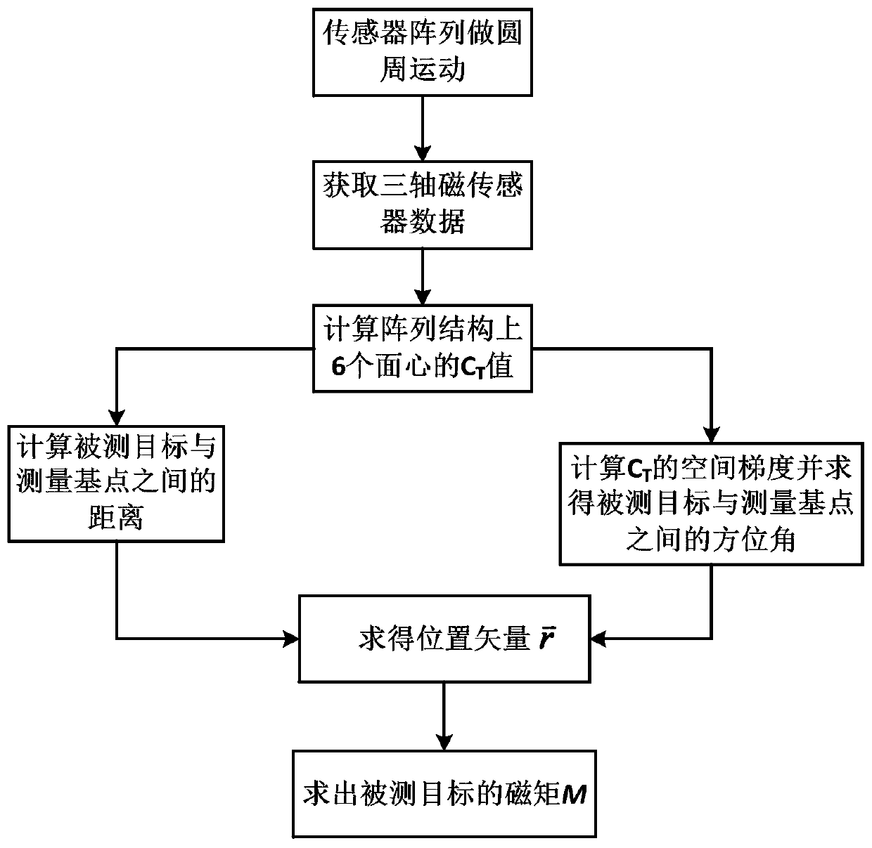
[0088] In this embodiment, on the basis of Embodiment 1, multiple position detections are used to improve positioning accuracy. Such as Figure 6 As shown, the measurement baseline 1 and the measurement baseline 2 are perpendicular to each other, and the measurement points A and B are respectively located on the two measurement baselines. The rotating mechanism is equipped with a magnetic sensor array, and the magnetic anomaly target is detected at the measurement point A, and the magnetic anomaly signal of the three axes of the magnetic sensor is obtained according to Embodiment 1, and the target position vector is calculated by using the target positioning algorithm and the target magnetic moment Use the trolley 9 to transfer the target detection device to the measurement point B, and repeat the magnetic anomaly target detection work at the measurement point A. Combined with the characteristics of the magnetic anomaly signal curves in various directions, the parameters su...


PUM


Abstract

The invention provides a magnetic sensor array based rotation-movement magnetic anomaly target detection device and method. The device comprises a magnetic sensor array, a rotation mechanism, a rotation angle collection module, a GPS module, a signal collection module, a data processing module and a power supply. The geographic coordinate of a detected target is determined according to magnetic field information, collected by the magnetic sensor array, of the magnetic anomaly target, the rotation angle of the rotation mechanism, and the real-time geographic position of the magnetic sensor array. Dynamic measurement is carried out by circular motion, more comprehensive magnetic anomaly information is obtained, and a positioning result is more accurate.

Description

technical field [0001] The invention belongs to the technical field of magnetic anomaly target detection, and specifically relates to a rotating motion magnetic anomaly target detection device and method based on a magnetic sensor array. Background technique [0002] The geomagnetic field is a natural physical field of the earth, which generally changes slowly and regularly with time and space. The ferromagnetic target is magnetized in the geomagnetic field environment, and the magnetization field and the geomagnetic field are superimposed on each other, resulting in the distribution of the magnetic field in the vicinity of the target. changes, that is, magnetic anomalies. Ferromagnetic metal deposits buried underground, oil and gas pipelines underground in cities, unexploded bombs left over during wars or military exercises, underwater military equipment such as submarines, mines and other objects all contain ferromagnetic components, resulting in abnormalities in the surro...

Claims


Application Information

Patent Timeline
Patent Type & Authority Applications(China)
IPC IPC(8): G01V3/08G01V3/38G01C21/00
CPCG01C21/005G01V3/081G01V3/38
Inventor 钟名尤卞雷祥葛闯李佳阳王明洋戎晓力韩松彤朱志伟贾云飞田巳睿
Owner NANJING UNIV OF SCI & TECH
Learn More