
Modular friction and wear testing machine and testing method thereof

A friction and wear test, modular technology, applied in the direction of testing wear resistance, measuring devices, instruments, etc., can solve the problems of easy disassembly and cleaning of internal parts, adverse effects on experimental accuracy, single use function, etc., to reduce vibration interference , reducing the impact of results, the effect of functional diversification

Pending Publication Date: 2019-10-08
GUIZHOU UNIV
View PDF0 Cites 9 Cited by
  • Summary
  • Abstract
  • Description
  • Claims
  • Application Information

AI Technical Summary

Problems solved by technology

[0003] Most of the current friction and wear testing machines are integral equipment, and the internal parts are not easy to disassemble and clean. During the test, vibration interference in irregular directions is likely to affect the results, adversely affect the accuracy of the experiment, and the use function is single

Method used


Image

  • Modular friction and wear testing machine and testing method thereof
  • Modular friction and wear testing machine and testing method thereof
  • Modular friction and wear testing machine and testing method thereof

Examples


Embodiment 1

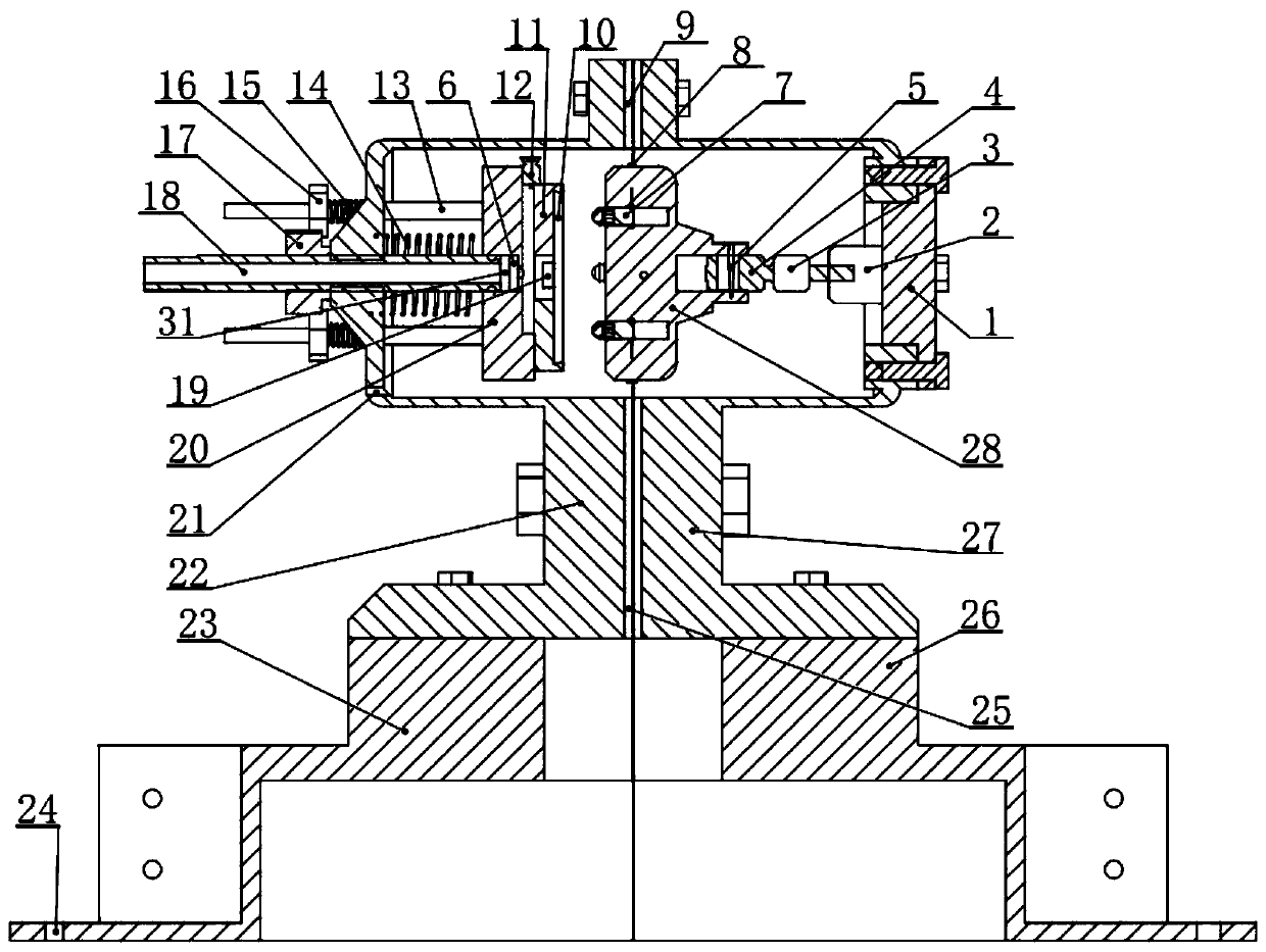
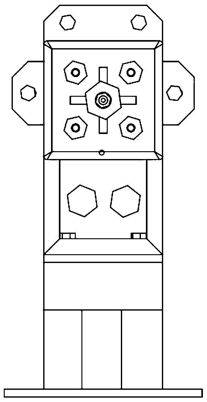
[0027] Embodiment 1: as Figure 1-Figure 6 As shown, a modular friction and wear testing machine includes a housing, a friction disc 28, a sample holding device, a loading device, a pressure sensor 6, a wireless torque sensor 3 and a stepping motor 2, and a loading device is installed on the left side of the housing. device, the inner end of the loading device is connected to the sample clamping device, a stepping motor 2 is installed on the left side of the housing, the motor shaft of the stepping motor 2 is connected to the transmission shaft 4 through the wireless torque sensor 3, and the transmission shaft 4 is axially movable In the blind hole on the connection friction disc 28, the friction disc 28 faces the sample clamping device, the pressure sensor 6 is installed on the inner end of the transmission shaft 4 and leans against the blind hole, and the end surface of the friction disc 28 facing the direction of the sample is installed with a protruding A plurality of even...

Embodiment 2

[0036] Embodiment 2: A test method of a modular friction and wear testing machine, the method is: first check whether the parts of each part are complete, and then install the sample on the sample clamping device to ensure reliable clamping, and install four Positioning rod and loading stud, and install a large spring on the loading stud, install the entire sample clamping device on the transparent shell 1 on the left, and pre-tighten it with the lock nut outside the shell 1, and then fine-tune it The fine-tuning nut in the mechanism carries out the positive position of the sample, and the external observation adjusts it to be vertical, and then the friction disc equipped with the pressure sensor is connected to the motor shaft of the stepping motor through the transmission shaft equipped with the wireless torque sensor, and then the electrochemical The temperature access point of the workstation is connected to the temperature sensor, and then the working electrode and the aux...


PUM


Abstract

The invention discloses a modular friction and wear testing machine and a testing method thereof, and the testing machine comprises a shell, a friction disc, a sample clamping device, a loading device, a pressure sensor, a wireless torque sensor and a stepping motor, wherein the left side of the shell is installed with the loading device, the inner end of the loading device is connected to the sample clamping device, the stepping motor is mounted on the left side of the shell, the motor shaft of the stepping motor is connected to a driving shaft through the wireless torque sensor, the drivingshaft is movably connected to a blind hole on the friction disc, the friction disc faces directly the sample clamping device, the pressure sensor is mounted on the inner end of the driving shaft and abuts in the blind hole, the end surface of the friction disc is mounted with a plurality of uniformly distributed projecting friction rods, the top, the bottom side and the bottom center of the shellare respectively provided with a top access hole, a side access hole and a residual liquid collecting hole, and a temperature sensor mounted on the sample is further provided. The modular friction andwear testing machine provided by the invention has the advantages of convenient operation, simple disassembly and assembly, stable load, diversified functions and modular design, is suitable for friction corrosion abrasion test under various conditions, and has wide application range.

Description

technical field [0001] The invention relates to a modularized friction and wear testing machine and a testing method thereof, belonging to the technical field of friction and wearing testing machines. Background technique [0002] Friction and wear refers to the physical and chemical phenomena that occur when two contact surfaces move relative to each other. It can be extended to salt spray corrosion wear, liquid erosion wear, and indirect immersion wear. In these cases, the frictional movement has concealment and measurement uncertainty, and its hazards are obvious in production. Friction and wear can cause damage to the material contact surface, cracks, and even lead to the failure of the entire system. Studies by relevant research institutions have shown that about a quarter of the world's annual energy consumption is on friction and wear and its incidental effects, resulting in a large amount of waste in the national economy, and four-fifths of the kinematic pair failure...

Claims


Application Information

Patent Timeline
Patent Type & Authority Applications(China)
IPC IPC(8): G01N3/56G01N3/02G01N3/04G01N17/00
CPCG01N3/56G01N3/02G01N3/04G01N17/00
Inventor 唐正强土旗赵一舟惠佳博贾通李俨
Owner GUIZHOU UNIV
Learn More