
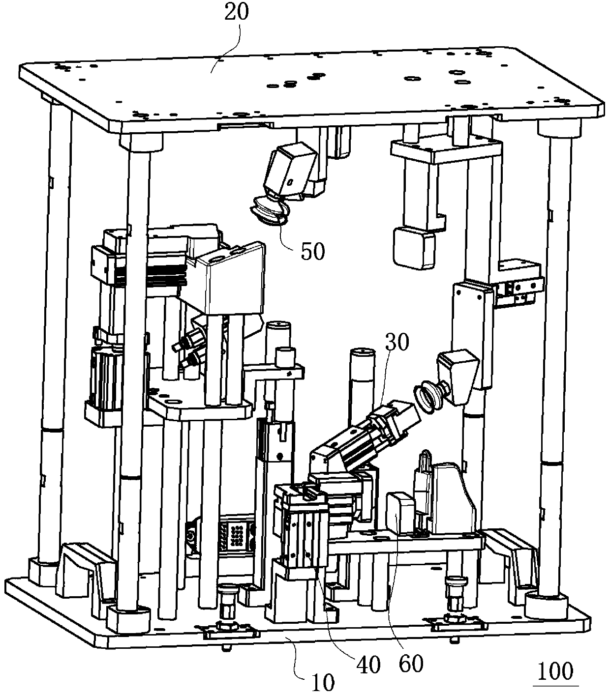
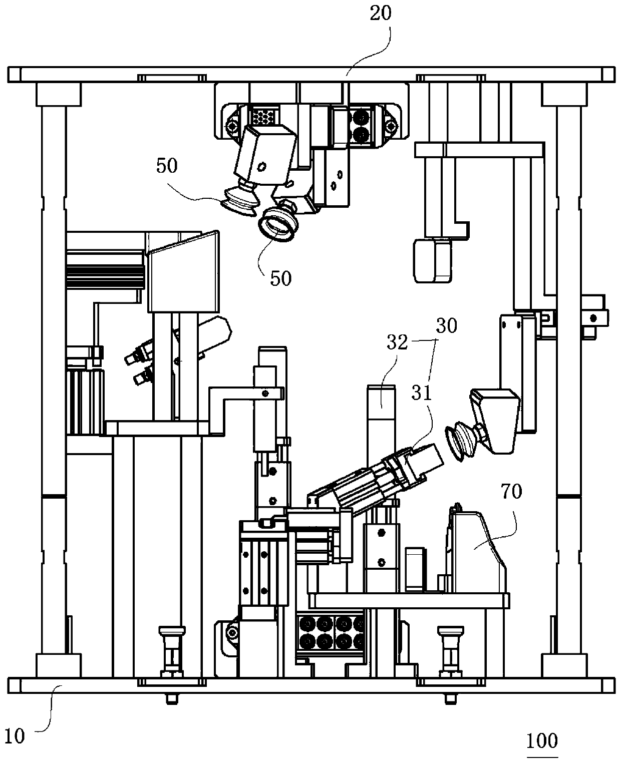
Light fixture detecting device

A technology for detection devices and lamps, which is applied in the direction of lamp testing, testing electrical devices in transportation, liquid tightness measurement using liquid/vacuum degree, etc. It can solve the problem of high staffing requirements, scratches on lamp products, and influence on product appearance and other issues to achieve the effect of streamlining staffing, improving production efficiency and product quality, and saving space for site layout

Pending Publication Date: 2019-10-08
CHANGZHOU XINGYU AUTOMOTIVE LIGHTING SYST CO LTD
View PDF0 Cites 0 Cited by
  • Summary
  • Abstract
  • Description
  • Claims
  • Application Information

AI Technical Summary

Problems solved by technology

The existing design scheme first has the disadvantages of scratches and scratches on the lighting products, which affects the appearance of the product; secondly, it is time-consuming and laborious, which affects production and reduces production efficiency; finally, it requires high staff configuration.

Method used


Image

  • Light fixture detecting device
  • Light fixture detecting device
  • Light fixture detecting device

Examples


Embodiment Construction

[0032] Embodiments of the present invention are described in detail below, examples of which are shown in the drawings, wherein the same or similar reference numerals designate the same or similar elements or elements having the same or similar functions throughout. The embodiments described below by referring to the figures are exemplary only for explaining the present invention and should not be construed as limiting the present invention.

[0033] In describing the present invention, it should be understood that the terms "center", "longitudinal", "transverse", "length", "width", "thickness", "upper", "lower", "front", " Back", "Left", "Right", "Vertical", "Horizontal", "Top", "Bottom", "Inner", "Outer", "Clockwise", "Counterclockwise", "Axial", The orientation or positional relationship indicated by "radial", "circumferential", etc. is based on the orientation or positional relationship shown in the drawings, and is only for the convenience of describing the present invent...


PUM


Abstract

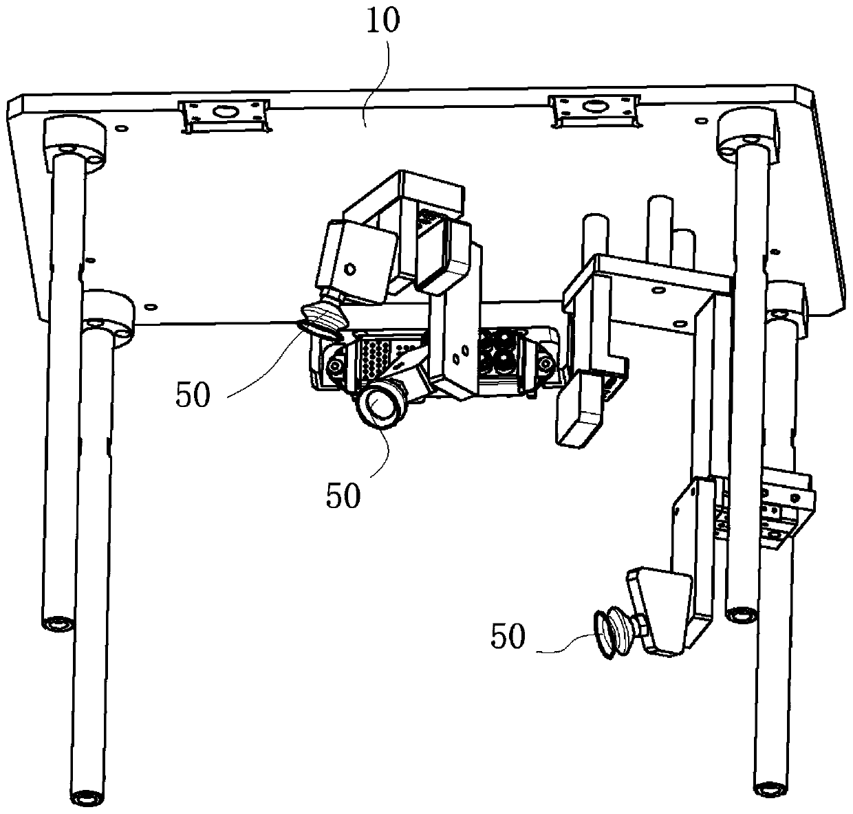
The invention discloses a light fixture detecting device comprising a lower template, an upper template, an airtight detecting member, an electric detecting member, and an absorbing member. The lowertemplate is used for carrying a light fixture product. The upper template is arranged above the lower template; and receiving space is limited between the upper template and the lower template. The airtight detecting member that is disposed at the lower template in the receiving space is capable of carrying out positive pressure airtight detection on a light fixture product. The electric detectingmember that is disposed at the lower template in the receiving space is capable of carrying out electric detection on the light fixture product. The absorbing member is arranged at the upper template; an absorbing surface is formed at the at least one part of the absorbing member and is capable of absorbing or loosening the light fixture product. Therefore, the light fixture product can be absorbed or captured automatically; and gas-electric integrated function detection can be realized.

Description

technical field [0001] The invention relates to a lamp detection device. Background technique [0002] In automated production, companies need to meet customers' high requirements for product quality and new technology needs. At present, almost all products in the car lamp project involve the functional requirements of air tightness detection and electrical inspection of lamps and lanterns. The functional requirements of air tightness detection and electrical inspection and detection are completed in the conventional way as follows: 1. The air tightness detection tooling of lamps alone meets the requirements Its functional requirements; 2. It can meet its functional requirements through the electric inspection and detection tooling of the lamp alone. The existing design scheme firstly has the disadvantages of scratches and scratches on the lighting products, which affects the appearance of the product; secondly, it is time-consuming and laborious, which affects production a...

Claims


Application Information

Patent Timeline
Patent Type & Authority Applications(China)
IPC IPC(8): G01M3/02G01R31/44
CPCG01M3/02G01R31/44G01R31/005
Inventor 曹芬娟王亚飞沈毅
Owner CHANGZHOU XINGYU AUTOMOTIVE LIGHTING SYST CO LTD
Learn More