
Automatic spraying type agricultural unmanned aerial vehicle

An automatic spraying and drone technology, applied in the field of drones, can solve problems such as inconvenient return of the drone body, lack of liquid level monitoring capabilities, and inability to adjust the spraying angle, so as to achieve excellent mechanical properties and improve flight capabilities , the effect of reducing energy consumption

Pending Publication Date: 2019-10-08
珠海银通无人机科技有限公司
View PDF1 Cites 1 Cited by
  • Summary
  • Abstract
  • Description
  • Claims
  • Application Information

AI Technical Summary

Problems solved by technology

[0002] Unmanned aerial vehicles are unmanned aircraft that utilize radio remote control equipment and self-contained program control devices to manipulate, or are completely or intermittently operated autonomously by on-board computers. In the prior art: the patent of authorized publication number CN 207185734 U discloses An automatic spraying agricultural unmanned aerial vehicle, its structure includes a landing gear, a rotator, blades, a flight main control board, a drone main body, a fixed ring, a camera, a water pump, an automatic spraying device, and the flight main control board and The main body of the UAV is connected in an interference fit manner, and a camera is provided at the lower end of the main flight control board, which does not have the measurement capability, is inconvenient for quantitative spraying, cannot perform scientific operations, and cannot adjust the spraying angle. It is not convenient to deal with different wind speed environments, it does not have the ability to monitor the liquid level, and it is not convenient to return the drone body in time when the spray liquid is used up

Method used


Image

  • Automatic spraying type agricultural unmanned aerial vehicle
  • Automatic spraying type agricultural unmanned aerial vehicle
  • Automatic spraying type agricultural unmanned aerial vehicle

Examples


Embodiment Construction

[0024] The following will clearly and completely describe the technical solutions in the embodiments of the present invention with reference to the accompanying drawings in the embodiments of the present invention. Obviously, the described embodiments are only some, not all, embodiments of the present invention. Based on the embodiments of the present invention, all other embodiments obtained by persons of ordinary skill in the art without making creative efforts belong to the protection scope of the present invention.

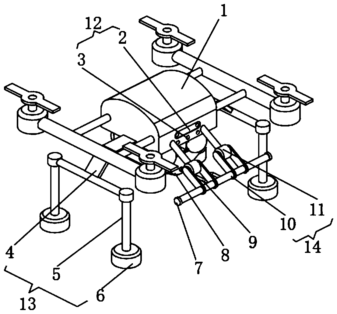
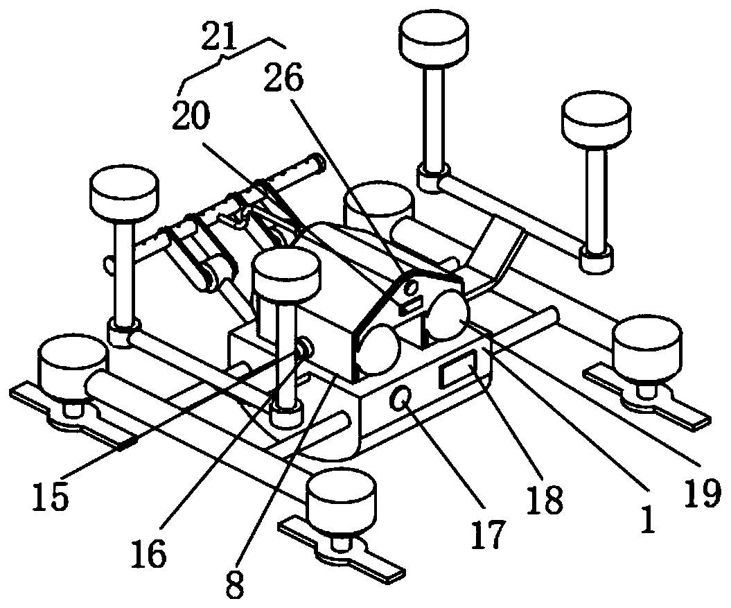
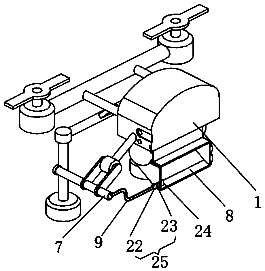
[0025] see Figure 1-3 , the present invention provides a technical solution: an automatic spraying agricultural unmanned aerial vehicle, comprising an unmanned aerial vehicle body 1, an angle adjustment device 14, a single-chip microcomputer 17, a power supply 18 and an environmental monitoring device are respectively installed on the sides of the unmanned aerial vehicle main body 1 12. The landing gear 13 and the water tank 8 are respectively installed on th...


PUM


Abstract

The invention discloses an automatic spraying type agricultural unmanned aerial vehicle. The automatic spraying type agricultural unmanned aerial vehicle comprises an unmanned aerial vehicle body, wherein an angle adjusting device, a single-chip microcomputer, a power supply and an environment monitoring device are mounted on the side surface of the unmanned aerial vehicle body correspondingly, the bottom of the unmanned aerial vehicle body is correspondingly provided with a landing frame and a water tank, the side surface of the water tank communicates with a water inlet pipe, a switch valveis arranged at the joint between the water inlet pipe and the water tank, a liquid level monitoring device is arranged on the side surface of the water tank, the end part of the angle adjusting deviceis provided with a spraying pipe, and the spraying pipe communicates with the interior of the water tank through a threaded telescopic pipe. The automatic spraying type agricultural unmanned aerial vehicle has the advantages that a machine body of the unmanned aerial vehicle body is of a streamline structure, so that the flight resistance is reduced, then the energy consumption is reduced, and the flying capability of the agricultural unmanned aerial vehicle is greatly improved; and a shell of the unmanned aerial vehicle body is an ABS shell, and ABS has excellent mechanical properties, so that the overall strength of the unmanned aerial vehicle body is improved.

Description

technical field [0001] The invention relates to the technical field of drones, in particular to an automatic spraying agricultural drone. Background technique [0002] Unmanned aerial vehicles are unmanned aircraft that utilize radio remote control equipment and self-contained program control devices to manipulate, or are completely or intermittently operated autonomously by on-board computers. In the prior art: the patent of authorized publication number CN 207185734 U discloses An automatic spraying agricultural unmanned aerial vehicle, its structure includes a landing gear, a rotator, blades, a flight main control board, a drone main body, a fixed ring, a camera, a water pump, and an automatic spraying device, and the flight main control board and The main body of the UAV is connected in an interference fit manner, and a camera is provided at the lower end of the flight main control board, which does not have the measurement capability, is inconvenient for quantitative sp...

Claims


Application Information

Patent Timeline
IPC IPC(8): B64C39/02B64D1/18A01M7/00G01D21/02G05D27/02
CPCA01M7/0042A01M7/005A01M7/0082A01M7/0085A01M7/0089B64C39/02B64D1/18G01D21/02G05D27/02
Inventor 黄彰标
Owner 珠海银通无人机科技有限公司
Learn More