A cleaning device for hemorheological instruments

A cleaning device and blood rheology technology, which is applied to chemical instruments and methods, cleaning methods and utensils, cleaning methods using liquids, etc., can solve the problems of occupation of personnel's working time, water splashing, etc., and save the time of manual cleaning , to avoid the effect of deformation

Active Publication Date: 2022-03-29
QINGDAO CENT HOSPITAL
View PDF0 Cites 0 Cited by
  • Summary
  • Abstract
  • Description
  • Claims
  • Application Information

AI Technical Summary

Problems solved by technology

[0003] Most of the existing blood rheometers have the function of self-cleaning, but this function is often limited to the cleaning of the internal pipeline of the instrument itself. For the rotating cone and the centering cover outside the cone, it needs to be cleaned manually , when there are many detection items, it will take up the working time of the personnel
But because the cone and the centering cover are located outside the shell of the instrument, if they are washed directly with water, it is easy to cause the cleaning water to splash

Method used


Image

  • A cleaning device for hemorheological instruments
  • A cleaning device for hemorheological instruments
  • A cleaning device for hemorheological instruments

Examples


Embodiment 1

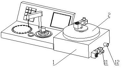
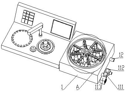
[0040] see figure 1 and figure 2 , the present invention provides a cleaning device for blood rheological instruments, including a base 1 provided with a cleaning chamber, a top cover 2 is provided on the top of the base 1, and a water inlet communicating with the cleaning chamber is provided on one side of the base 1 11 and the water outlet 12, the pipelines of the water inlet 11 and the water outlet 12 are all provided with solenoid valves, and the pipelines are controlled to open and close through the solenoid valves;

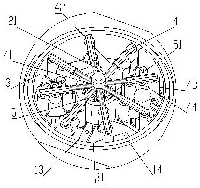
[0041] The cleaning chamber is rotated and connected to the cleaning pool 3. The cleaning pool 3 includes two parts that are separated and symmetrical; the bottom of the cleaning pool 3 is grid-shaped; The bottom plate is provided with a number of jet ports 13 for jetting water, and an ultrasonic vibrating plate 14;

[0042] The cleaning chamber is a cylindrical cavity, and the cleaning pool 3 includes two fan-shaped pool bodies symmetrically arranged. Th...

Embodiment 2

[0049] see Figure 1 to Figure 6 , On the basis of Embodiment 1, different from Embodiment 1, this device includes a base 1 provided with a cleaning chamber, a top cover 2 is provided on the top of the base 1, and a cleaning chamber is provided on one side of the base 1. The water inlet 11 and the water outlet 12 connected in the chamber are provided with electromagnetic valves on the pipelines of the water inlet 11 and the water outlet 12, and the opening and closing of the pipelines are controlled by the electromagnetic valves;

[0050] The cleaning chamber is rotated and connected to the cleaning pool 3. The cleaning pool 3 includes two parts that are separated and symmetrical; the bottom of the cleaning pool 3 is grid-shaped; The bottom plate is provided with a number of jet ports 13 for jetting water, and an ultrasonic vibrating plate 14;

[0051] The cleaning chamber is a cylindrical cavity, and the cleaning pool 3 includes two fan-shaped pool bodies symmetrically arran...

Embodiment 3

[0074] On the basis of Embodiment 2, the difference from Embodiment 2 is that the external port 21 is fixedly connected to the three-way valve 111 , and the lower end of the center column 41 is inserted into the upper end of the gear shaft of the driving wheel 5 . Such a connection mode does not need to disassemble the three-way valve 111 when picking up the top cover 2 .


PUM


Abstract

The invention discloses a cleaning device for blood rheological instruments, which relates to the technical field of medical equipment cleaning. The water inlet and the water outlet connected in the cleaning chamber are provided with electromagnetic valves on the pipelines of the water inlet and the water outlet, and the opening and closing of the pipelines are controlled by the electromagnetic valves. The beneficial effects of the present invention are: the device can automatically clean the liquid cutting cone, the centering cover and other devices that need to be removed from the hemorheometer for cleaning, and different parts can be placed separately, thereby avoiding the gap between the components of the hemorheometer. The deformation caused by the collision during cleaning will affect the detection effect of the hemorheometer. After the device is cleaned, the cleaned parts can also be dried and stored, and placed inside for later use, which can save the time of manual cleaning and complete the cleaning of parts without manual management.

Description

technical field [0001] The invention relates to the technical field of medical equipment cleaning, in particular to a cleaning device for hemorheological instruments. Background technique [0002] Hemorheology is a blood clinical testing instrument developed on the basis of the theory of hemorheology. It is a special testing instrument for early diagnosis of diseases by testing the viscosity of human blood. [0003] Most of the existing blood rheometers have the function of self-cleaning, but this function is often limited to the cleaning of the internal pipeline of the instrument itself. For the rotating cone and the centering cover outside the cone, it needs to be cleaned manually , when there are many detection items, it will take up the working time of the personnel. But because both the cone and the centering cover are located outside the shell of the instrument, if they are directly washed with water, it is easy to cause splashing of cleaning water. Contents of the ...

Claims


Application Information

Patent Timeline
Patent Type & Authority Patents(China)
IPC IPC(8): B08B3/02B08B3/10B08B3/12
CPCB08B3/022B08B3/10B08B3/123
Inventor 王金乐赵风雪张蓉
Owner QINGDAO CENT HOSPITAL
Why Eureka
Try Eureka