
Eccentric arc-shaped ring corridor segment high-altitude lifting tool and lifting method thereof

A ring corridor and arc-shaped technology, which is applied in the direction of lifting devices, lifting frames, auxiliary devices, etc., can solve the problems of inability to form butt joint welding, eccentric deflection of eccentric arc ring corridor sections, and inability to adjust attitude at high altitudes. It achieves simple structure, High installation efficiency and smooth connection

Pending Publication Date: 2019-10-01
CHINA MCC5 GROUP CORP
View PDF8 Cites 1 Cited by
  • Summary
  • Abstract
  • Description
  • Claims
  • Application Information

AI Technical Summary

Problems solved by technology

[0004] The technical problem to be solved by the present invention is: to provide high-altitude lifting tooling and its lifting method for the eccentric arc-shaped ring corridor section in the prior art, so as to solve the deflection due to eccentricity in the high-altitude lifting of the eccentric arc-shaped ring corridor section in the prior art, and at the same time, the attitude cannot be adjusted at high altitude , leading to the problem that it cannot be welded and formed after lifting

Method used


Image

  • Eccentric arc-shaped ring corridor segment high-altitude lifting tool and lifting method thereof
  • Eccentric arc-shaped ring corridor segment high-altitude lifting tool and lifting method thereof
  • Eccentric arc-shaped ring corridor segment high-altitude lifting tool and lifting method thereof

Examples


Embodiment Construction

[0027] The present invention will be further described below with reference to the accompanying drawings and embodiments, and the mode of the present invention includes but not limited to the following embodiments.

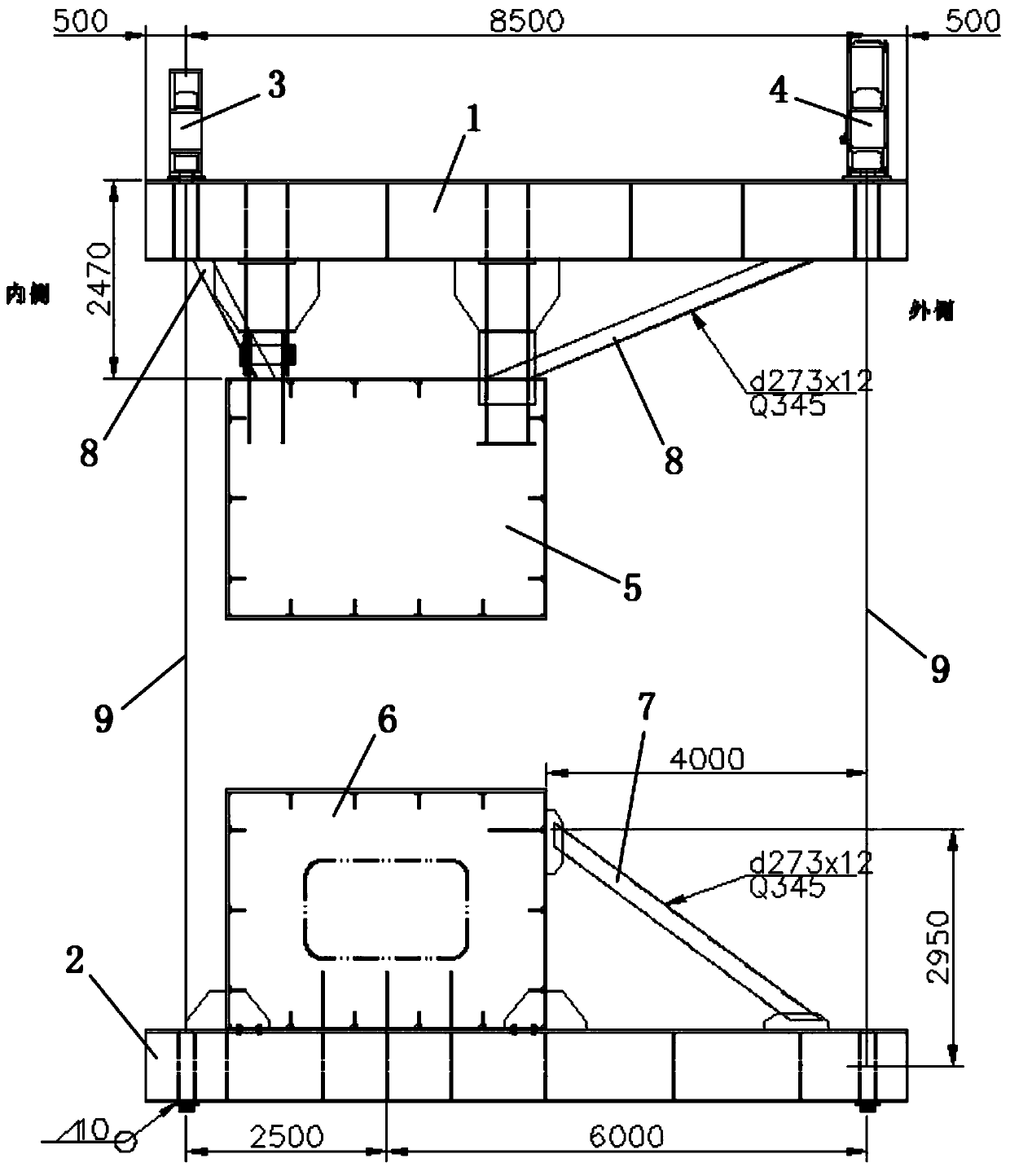
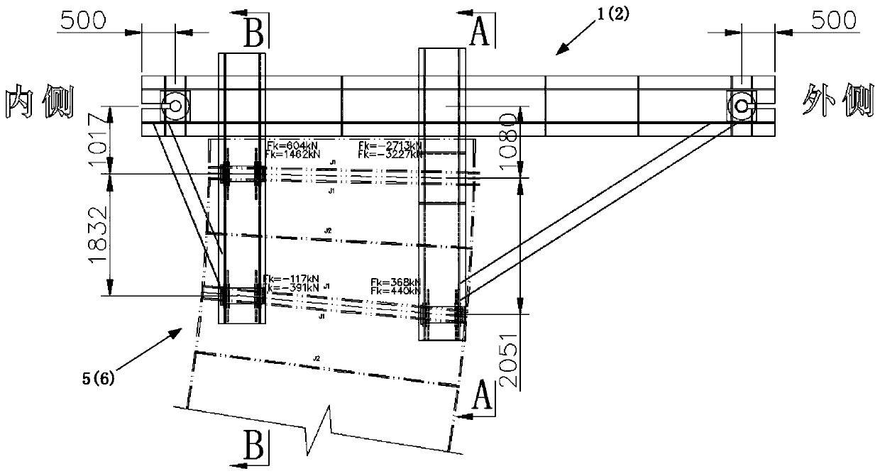
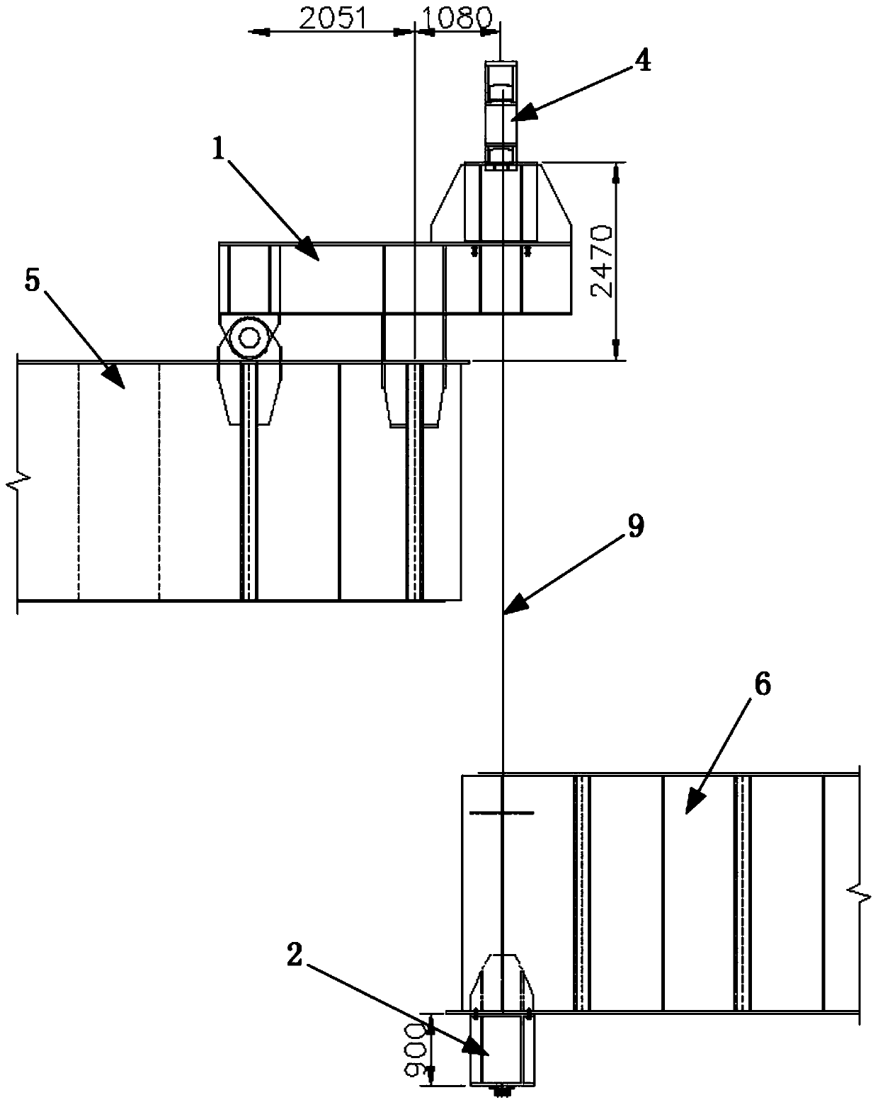
[0028] like Figure 1-4 As shown, the high-altitude lifting tooling for the eccentric arc-shaped ring corridor section provided by the present invention has a simple structure, scientific and reasonable design, and is easy to use. To ensure that the eccentric arc ring section does not deflect during lifting, to ensure the safety of the lifting process, and after the lifting is in place, the joints are connected smoothly, the welding is convenient, and the installation efficiency is improved. The present invention is used to elevate the eccentric arc-shaped ring corridor section 6 located on the ground in the segmented high-altitude ring corridor to a height of 100m, and separate its two ends from the high-altitude arc-shaped ring corridor section fixed at an altit...


PUM


Abstract

The invention discloses an eccentric arc-shaped ring corridor segment high-altitude lifting tool and a lifting method thereof. The problem that when an eccentric arc-shaped ring corridor segment in the prior art is lifted, deflection caused by eccentricity causes the condition that opening-aligned welding molding cannot be achieved after lifting is solved. The high-altitude lifting tool comprisesupper lifting outwards-extending type cantilever steel beams, lower lifting outwards-extending type cantilever steel beams, first lifting oil cylinders and second lifting oil cylinders. The lifting method mainly comprises the steps of correspondingly installing the upper lifting outwards-extending type cantilever steel beams and the lower lifting outwards-extending type cantilever steel beams on high-altitude arc-shaped ring corridor segments and eccentric arc-shaped ring corridor segments correspondingly, the lower lifting outwards-extending type cantilever steel beams are connected with thefirst lifting oil cylinders and the second lifting oil cylinders through steel wire ropes, and then the eccentric arc-shaped ring corridor segments can be raised to the 100 m high altitude at the constant speed and are in opening-aligned connection with the two high-altitude arc-shaped ring corridor segments for welding and fixing. The outwards-extending type cantilever steel beams are arranged toadjust the core positions of the eccentric arc-shaped ring corridor segments, it is ensured that the eccentric arc-shaped ring corridor segments do not deflect during lifting, safety in the lifting process is ensured, and smooth aligned welding after lifting in place is achieved.

Description

technical field [0001] The invention relates to a high-altitude lifting tool for an eccentric arc ring gallery section and a lifting method thereof. Background technique [0002] The three super high-rise buildings are distributed at 120 degrees, with a height of nearly 100 meters; the current undertaking project needs to build a high-altitude ring corridor on the top of the three super high-rise buildings distributed at 120 degrees to form a circular passage, which will be used as a sightseeing walkway or office space after completion . It is no longer applicable to use the existing technology to install the ring corridor by erecting a support frame. Because it is difficult to install the high-altitude ring corridor when working at a height of 100 meters, the cost of erecting the support frame is high, the risk factor is high, and the cycle is long. The segmental installation method is used to install the high-altitude ring corridor to overcome the above defects. However, ...

Claims


Application Information

Patent Timeline
Patent Type & Authority Applications(China)
IPC IPC(8): B23K37/00B23K37/04B66F7/16
CPCB23K37/00B23K37/0426B66F7/16
Inventor 姜友荣杨猛李丽唐丽殷洪闫志强刘云辉
Owner CHINA MCC5 GROUP CORP
Learn More