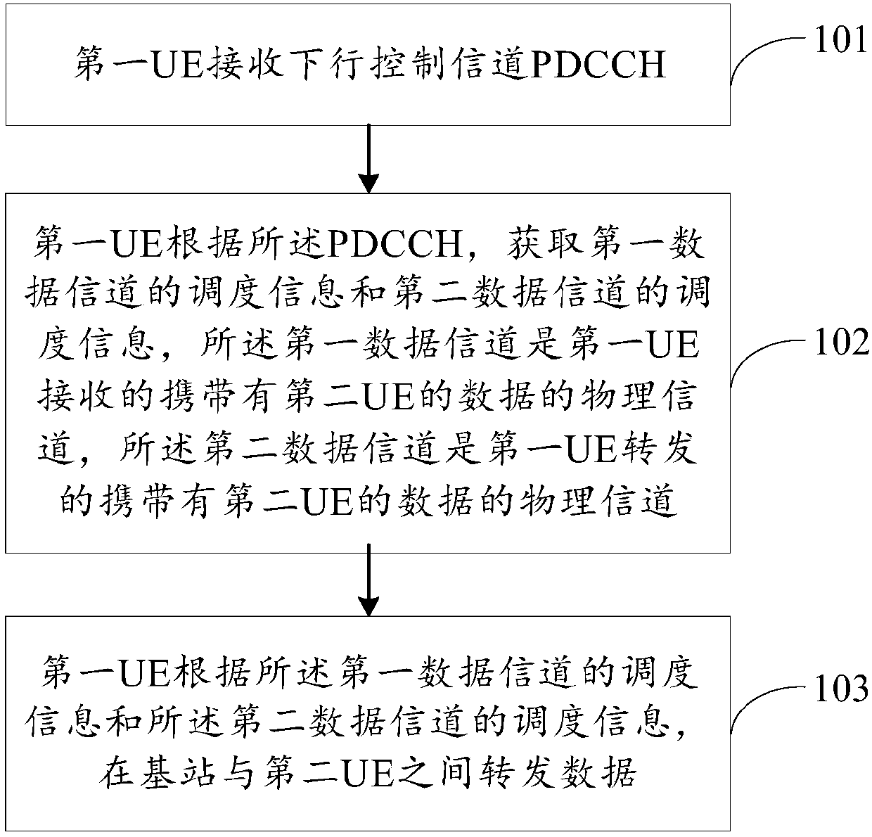
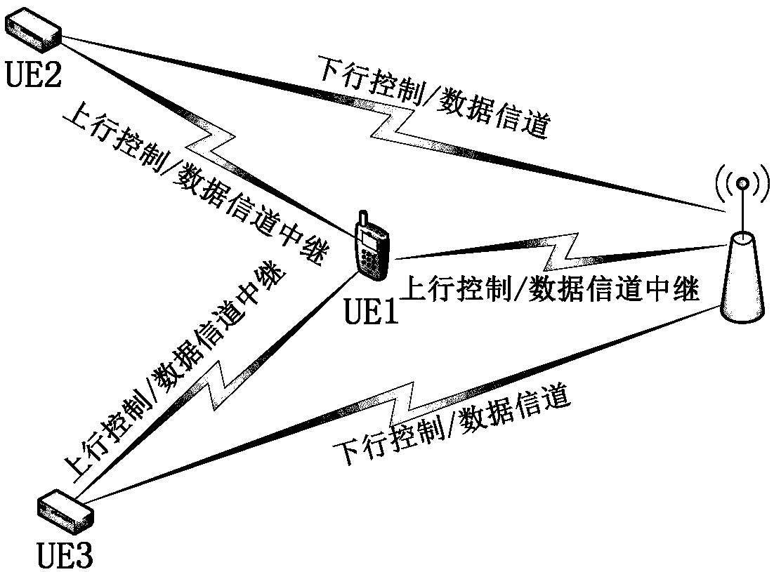
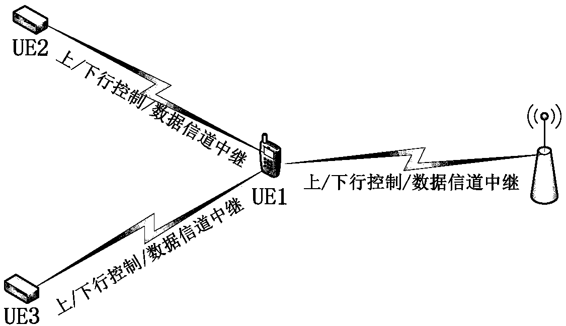
Relay transmission method and user equipment
A transmission method and retransmission technology, applied in transmission systems, digital transmission systems, transmission modification based on link quality, etc., can solve problems such as inability to guarantee service continuity, achieve service continuity, improve success rate, good The effect of compatibility
- Summary
- Abstract
- Description
- Claims
- Application Information
AI Technical Summary
Problems solved by technology
Method used
Image
Examples
Embodiment 1
[0144] Embodiment 1. Relay UE forwards downlink data and downlink control information
[0145] see Figure 5 , Figure 5 The communication process between the base station, the relay UE, and the remote UE in this embodiment is shown:
[0146] (1) The base station sends the first PDCCH (downlink control channel) to the relay UE, and the PDCCH indicates the following scheduling information of the first PDSCH, the second PDCCH and the second PDSCH.
[0147] (2) The base station sends the first PDSCH to the relay UE, and the PDSCH carries downlink data of the remote UE.
[0148] (3) The relay UE sends the second PDCCH to the remote UE, and the PDCCH indicates the scheduling information of the second PDSCH below.
[0149] (4) The relay UE sends the second PDSCH to the remote UE, and the PDSCH forwards the downlink data of the remote UE carried by the first PDSCH.
[0150] *Multiple possibilities of the first PDCCH
[0151] In this embodiment, the first PDCCH may include one or...
Embodiment 2
[0171] Embodiment 2. The relay UE only forwards downlink data and does not forward downlink control information (the first PDSCH and the second PDSCH are scheduled separately)
[0172] see Figure 6 , Figure 6 The communication process between the base station, the relay UE, and the remote UE in this embodiment is shown:
[0173] (1) The base station sends the first PDCCH to the relay UE, and the PDCCH indicates the scheduling information of the following first PDSCH.
[0174] (2) The base station sends the first PDSCH to the relay UE, and the PDSCH carries downlink data of the remote UE.
[0175] (3) The base station directly sends the second PDCCH to the remote UE, and the PDCCH indicates the scheduling information of the second PDSCH below.
[0176] (4) The relay UE monitors the above second PDCCH, and based on the scheduling information indicated by the second PDCCH, sends the second PDSCH to the remote UE, and the PDSCH forwards the downlink data of the remote UE carr...
Embodiment 3
[0181] Embodiment 3. The relay UE only forwards downlink data and does not forward downlink control information (the first PDSCH and the second PDSCH adopt the same scheduling)
[0182] see Figure 7 , Figure 7 The communication process between the base station, the relay UE, and the remote UE in this embodiment is shown:
[0183] (1) The base station directly sends the first PDCCH to the remote UE, and the PDCCH indicates the scheduling information of the following second PDSCH.
[0184] (2) The base station sends the first PDSCH to the relay UE, the PDSCH carries the data of the remote UE, and uses the same scheduling information as the following second PDSCH. The relay UE monitors the above first PDCCH, and receives the first PDSCH based on the scheduling information indicated by the first PDCCH.
[0185](3) The relay UE sends the second PDSCH to the remote UE based on the scheduling information indicated by the first PDCCH, and the PDSCH forwards the downlink data of t...
PUM
 Abstract
Description
Claims
Application Information
 - R&D
- Intellectual Property
- Life Sciences
- Materials
- Tech Scout
- Unparalleled Data Quality
- Higher Quality Content
- 60% Fewer Hallucinations
Browse by: Latest US Patents, China's latest patents, Technical Efficacy Thesaurus, Application Domain, Technology Topic, Popular Technical Reports.
© 2025 PatSnap. All rights reserved.Legal|Privacy policy|Modern Slavery Act Transparency Statement|Sitemap|About US| Contact US: help@patsnap.com


