Pyrotechnically actuated separation impact reduction device based on inverse wavelength characteristic and preparation process thereof

A technology of pyrotechnic separation and impact device, which is applied in the direction of friction shock absorber, etc., can solve the problems of damage to precision instruments, inability to effectively reduce impact, and reduce the stability of system structure, so as to achieve good adaptability and improve the impact reduction effect Effect

Pending Publication Date: 2019-09-27
XIAMEN UNIV +1
View PDF0 Cites 2 Cited by
  • Summary
  • Abstract
  • Description
  • Claims
  • Application Information

AI Technical Summary

Problems solved by technology

As we all know, after pyrotechnic separation, a shock wave with huge energy will be generated, and the shock wave will cause a large acceleration in the adjacent structure, which will cause damage to the precision instruments on the structure
In order to reduce the acceleration response, the precision instrument is usually arranged at the end away from the pyrotechnic separation, and the shock received is reduced by extending the transmission path of the shock. However, due to the limited length of the transmission path, the weakening of the shock response is limited.
Another way to deal with it is to add a buffer device in the path of shock wave transmission to reduce the impact received through buffering, but because the buffer device added in the path will reduce the stability of the entire system structure, and the joints Rigidity cannot be guaranteed
Therefore, neither extending the transmission path nor adding buffer devices can effectively reduce the impact received

Method used


Image

  • Pyrotechnically actuated separation impact reduction device based on inverse wavelength characteristic and preparation process thereof
  • Pyrotechnically actuated separation impact reduction device based on inverse wavelength characteristic and preparation process thereof
  • Pyrotechnically actuated separation impact reduction device based on inverse wavelength characteristic and preparation process thereof

Examples


Embodiment 1

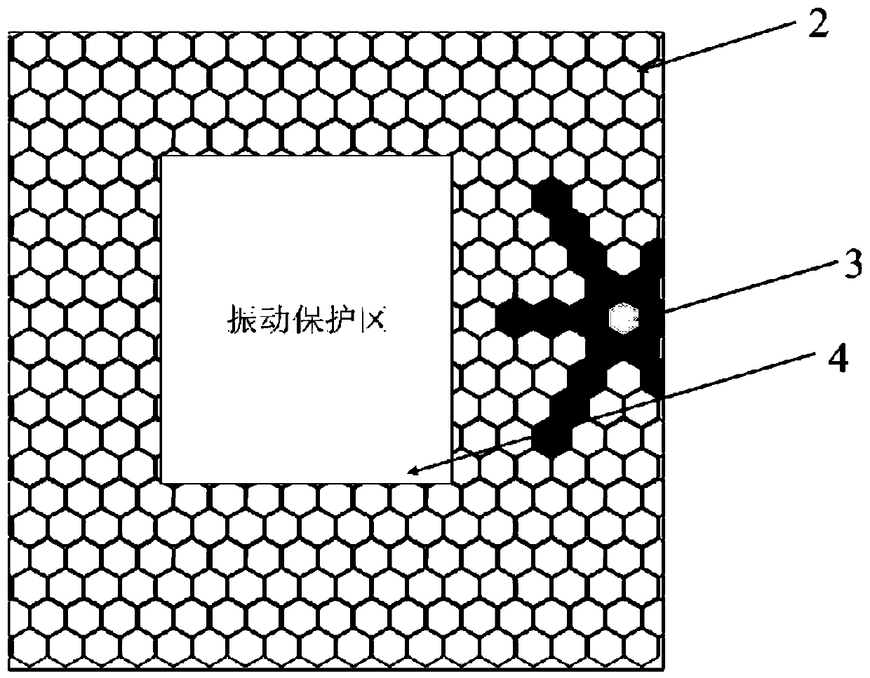
[0053] Please also see image 3 with Figure 4 ,in, image 3 A schematic diagram of the arrangement relationship of the cavity structure shown in this embodiment is shown, Figure 4 for image 3 side view. This figure shows the pyrotechnic separation and impact reduction device of the detonation bolt 3 type. When the pyrotechnic separation, the bolt 3 explodes, and the protected device is roughly located in the vibration protection zone 4 shown in the figure for illustration.

[0054] As shown in the figure, the position of the bolt 3 is the position where the pyrotechnic shock occurs, and the periodically arranged cavities 2 are arranged in a radial scattering form from the inside to the outside with this position as the center of the circle; That is, the cavity 2 shown in black in the figure is filled with damping particles.

[0055] The shock wave generated by the explosion of the bolt 3 will excite the damping particles filled in the cavity 2 arranged in the radial sc...

Embodiment 2

[0076] See Figure 7 , which shows a schematic diagram of the arrangement relationship of the cavity structure described in the second embodiment. In order to clearly show the differences and connections between this embodiment and Embodiment 1, structures with the same functions are indicated with the same reference numerals in the figure.

[0077] The core design concept of this solution is exactly the same as that of Embodiment 1. The difference in the arrangement of the cavity structure is that the periodically arranged cavity 2 is configured as follows: the position where the pyrotechnic impact occurs (bolt 3) is The center of the circle is nested and arranged around an arc from the inside to the outside; that is, the chamber 2 shown in dark gray in the figure is filled with damping particles. Implementation principles of other functions are the same as those in Embodiment 1, so details are not repeated here.

Embodiment 3

[0079] See Figure 8 , which shows a schematic diagram of the arrangement relationship of the cavity structure described in the third embodiment. In order to clearly show the differences and connections between this embodiment and Embodiments 1 and 2, structures with the same functions are shown with the same reference numerals in the figure.

[0080] The core design concept of this solution is exactly the same as that of Embodiment 1. The difference in the arrangement of the cavity structure is that the periodically arranged cavity 2 is configured as follows: the position where the pyrotechnic impact occurs (bolt 3) is The center of the circle is nested and arranged in a polygonal shape from the inside to the outside; that is, the cavity 2 shown in light gray in the figure is filled with damping particles. Implementation principles of other functions are the same as those in Embodiment 1, so details are not repeated here.


PUM

PropertyMeasurementUnit
Side lengthaaaaaaaaaa
Wall thicknessaaaaaaaaaa
Heightaaaaaaaaaa

Abstract

The invention discloses a pyrotechnically actuated separation impact reduction device based on an inverse wavelength characteristic and a preparation process thereof. A plurality of closed accommodating cavities which are distributed in sequence are formed in a to-be-separated component. Among the multiple accommodating cavities distributed in sequence, damping particles are arranged in the accommodating cavities which are distributed periodically with a pyrotechnically actuated impact occurring position as the circle center, and a resonance unit with a frequency bandwidth characteristic is formed; and since the damping particles are excited under impact, the resonance unit and impact waves can achieve a coupling effect. By applying the scheme, an inverse wavelength characteristic mechanism is introduced into the structural design of the impact reduction device, an obvious impact reduction effect can be obtained on the basis of the small additional mass, and accordingly, the connecting rigidity requirement of the device is effectively considered.

Description

technical field [0001] The invention relates to the technical field of pyrotechnic separation, in particular to a pyrotechnic separation and impact reduction device based on inverse wavelength characteristics and a preparation process thereof. Background technique [0002] In the prior art, pyrotechnic separation technology is widely used in various fields, and an impact reduction device for controlling the impact generated by pyrotechnic separation is essential. As we all know, after pyrotechnic separation, a shock wave with huge energy will be generated, and the shock wave will cause a large acceleration in the adjacent structure, thereby causing damage to the precision instruments on the structure. In order to reduce the acceleration response, precision instruments are usually arranged at the end away from the pyrotechnic separation, and the shock received is reduced by extending the transmission path of the shock. However, due to the limited length of the transmission pa...

Claims


Application Information

Patent Timeline
IPC IPC(8): F16F7/01
CPCF16F7/01
Inventor 肖望强罗元易吉利
Owner XIAMEN UNIV
Why Eureka
Try Eureka