
Oil residue mixing device for oil refining

A mixing device and oil residue technology, applied in mixers, mixers with rotating agitating devices, applications, etc., can solve the problems of slow growth and development of livestock, insufficient mixing, inconvenient operation, etc., and achieve uniform nutrient content and spraying Large area and environmental protection effect

Active Publication Date: 2019-09-27
鲁控环保(苏州)有限公司
View PDF8 Cites 0 Cited by
  • Summary
  • Abstract
  • Description
  • Claims
  • Application Information

AI Technical Summary

Problems solved by technology

[0004] The purpose of the present invention is to solve the problem that the existing oil residue mixing device does not mix the oil residue with nutritional ingredients comprehensively and fully, resulting in feeding the livestock after the oil residue is mixed, and the nutritional value of the edible oil residue of the livestock is low, resulting in the growth of livestock The development is slow, and the efficiency of the existing oil residue mixing device for mixing and agitating the oil residue is slow, the mixing of the oil residue is not sufficient and thorough, and when the oil residue is mixed, the oil residue is easy to splash out, causing environmental pollution, and the oil residue mixed After the device has mixed the oil residue, the oil residue in the mixing bin is prone to dust and impurities, resulting in a short shelf life for the oil residue storage, and the oil residue mixing device is not convenient for the staff to operate, and the oil residue mixing device is time-consuming to use laborious and inconvenient to operate, and a kind of oil residue mixing device for oil refining is proposed

Method used


Image

  • Oil residue mixing device for oil refining
  • Oil residue mixing device for oil refining
  • Oil residue mixing device for oil refining

Examples


Embodiment Construction

[0046] The technical solutions of the present invention will be clearly and completely described below in conjunction with the embodiments. Apparently, the described embodiments are only some of the embodiments of the present invention, not all of them. Based on the embodiments of the present invention, all other embodiments obtained by persons of ordinary skill in the art without creative efforts fall within the protection scope of the present invention.

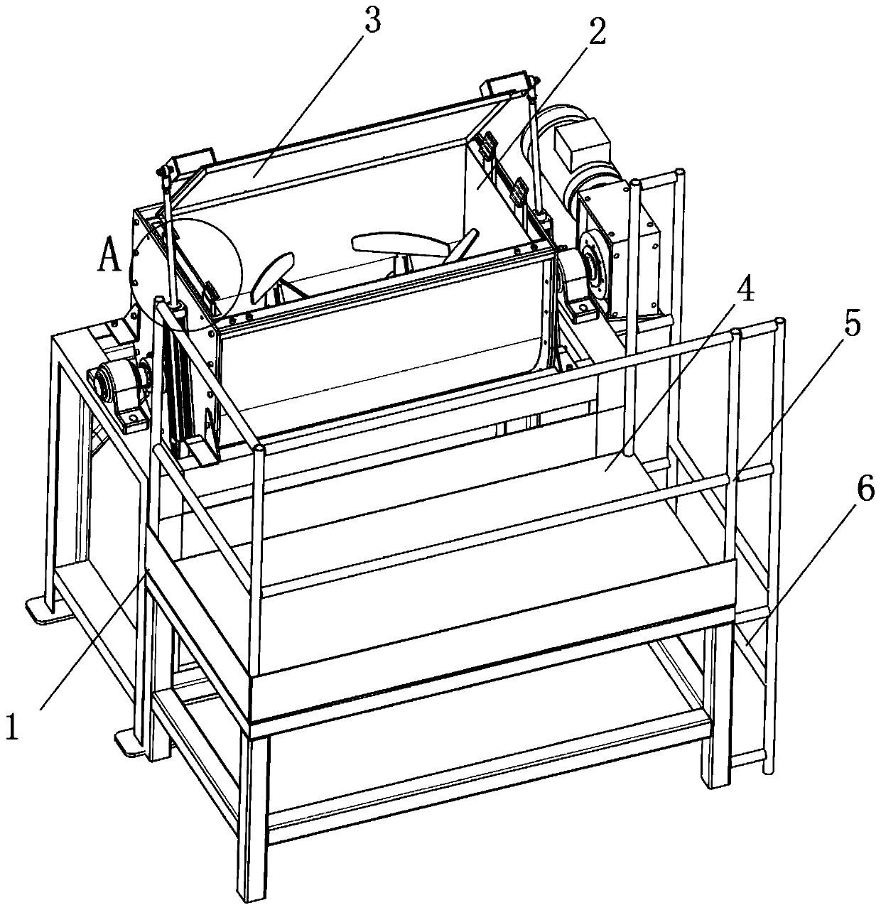
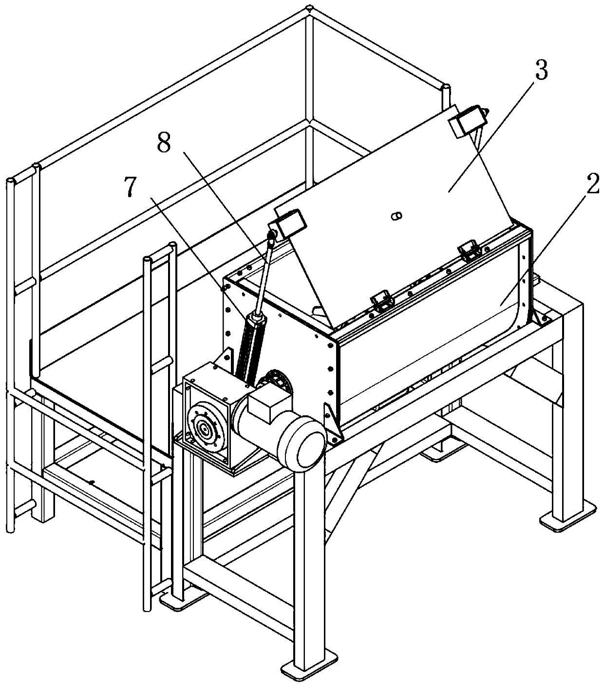
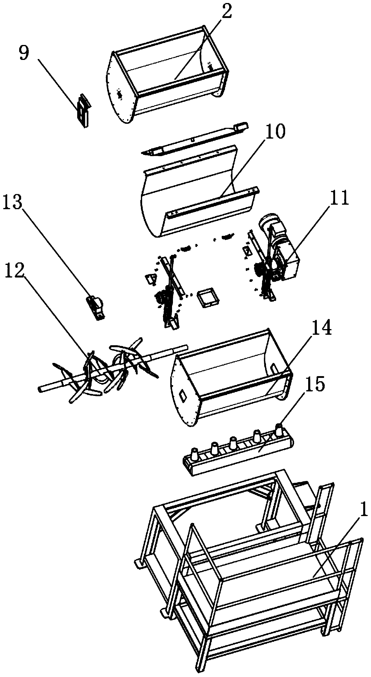
[0047] see Figure 1-12 As shown, an oil residue mixing device for oil refining includes a mounting bracket 1, an upper mixing box 2, an operating table 4, a handrail 5 and a ladder 6, and an upper mixing box 2 is arranged above one end of the mounting bracket 1, and the upper mixing A cover plate 3 is arranged above the box 2, an operation console 4 is arranged at one end of the installation bracket 1, and a handrail 5 is arranged on one side of the operation console 4, a step 6 is arranged under one end of the handrail 5,...


PUM


Abstract

The invention discloses an oil residue mixing device for oil refining. The oil residue mixing device comprises a mounting bracket, an upper mixing tank, an operation table, an armrest and a ladder, wherein the upper mixing tank is arranged above one end of the mounting bracket, a cover plate is arranged above the upper mixing tank, the operation table is arranged at one end of the mounting bracket, the armrest is arranged on one side of the operation table, and the ladder is arranged below one end of the armrest. Oil residues after oil refining are put into the upper mixing tank by staff, then the cover plate is driven to move downward by a hydraulic pump through a hydraulic rod, a mixing and stirring frame is driven by a first motor to rotate for mixing and stirring the oil residues, and at the same time of stirring, nutrient ingredients are sprayed on the oil residues in the upper mixing tank by two spray booths at the two ends of the upper mixing tank simultaneously, thus it is ensured that the oil residue and the nutrient ingredients are more evenly and fully mixed, it is also ensured that when the oil residue is mixed and prepared into a feed, the nutritional value is higher, and the nutrient content is more uniform and richer; the oil residue mixing device has good social benefits and is suitable for popularization.

Description

technical field [0001] The invention relates to an oil residue mixing device, in particular to an oil residue mixing device used for oil refining, and belongs to the application technical field of oil residue mixing devices. Background technique [0002] After the oil is refined, a large amount of oil residue will be produced. People use the oil residue mixing device to mix the oil residue produced by refining different oils with nutritional ingredients, and then feed them as feed to livestock. On the one hand, the waste of oil residue is avoided. On the other hand, it makes the nutrition taken by the livestock more balanced and accelerates the growth rate of the livestock. [0003] The existing oil residue mixing device for oil refining still has many deficiencies in use. The existing oil residue mixing device does not mix the oil residue with nutritional ingredients comprehensively and fully, resulting in the oil residue being mixed. Livestock feeding, the nutritional val...

Claims


Application Information

Patent Timeline
Patent Type & Authority Applications(China)
IPC IPC(8): B01F7/04B01F15/02A23K20/158
CPCA23K20/158B01F27/191B01F27/70B01F35/451B01F35/7179B01F2101/18
Inventor 曹清源
Owner 鲁控环保(苏州)有限公司
Learn More