
Rock cracking device of cutter suction ship

A cutter suction ship and rock-cracking technology, which is applied in the field of cutter suction ship rock-cracking devices, can solve problems such as high construction cost, low efficiency, and difficult control, and achieve the effect of high rock-cracking efficiency

Inactive Publication Date: 2019-09-24
裘世波
View PDF8 Cites 0 Cited by
  • Summary
  • Abstract
  • Description
  • Claims
  • Application Information

AI Technical Summary

Problems solved by technology

[0003] (1) Explode method with dynamite tree; Explosive is placed on reef surface and detonates, and its shortcoming explosive consumption is big, and efficiency is low;
[0004] (2) Drilling charge blasting method: use a professional drill ship to drill holes in underwater reefs, and after drilling, put explosives into the holes and then detonate. The disadvantages are complicated operation, high construction cost, and pollution;
[0005] (3) Hammering method: the heavy-duty impact hammer is lifted from the reef surface by a crane to release it at a certain height, and the impact hammer free-falls to impact the reef surface and crush the reef surface. Its disadvantages are difficult to control and low efficiency.

Method used


Image

  • Rock cracking device of cutter suction ship
  • Rock cracking device of cutter suction ship
  • Rock cracking device of cutter suction ship

Examples


Embodiment Construction

[0028] The specific implementation manners of the present invention will be further described in detail below in conjunction with the accompanying drawings and embodiments. The following examples are used to illustrate the present invention, but are not intended to limit the scope of the present invention.

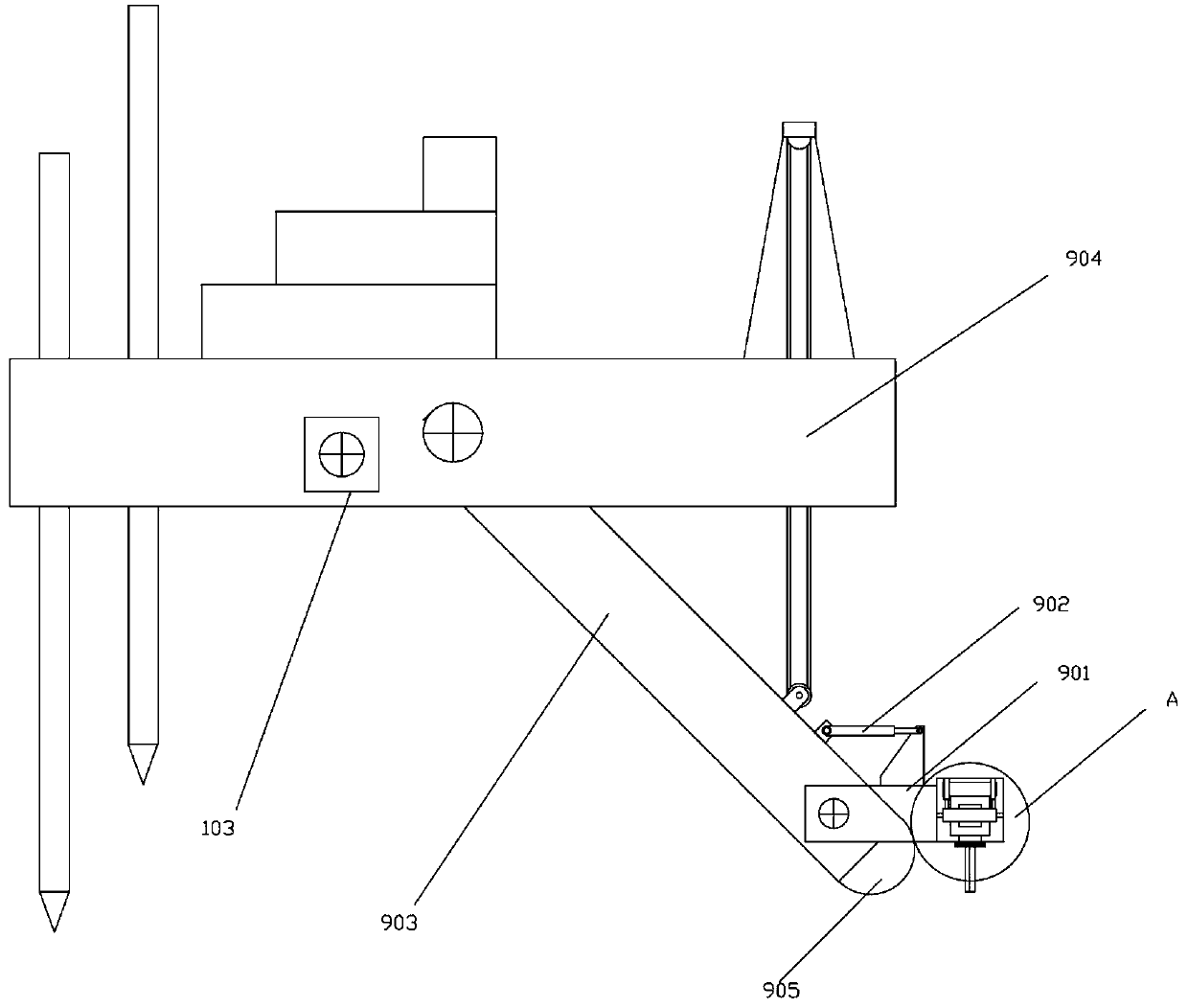
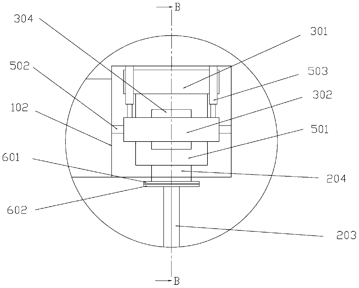
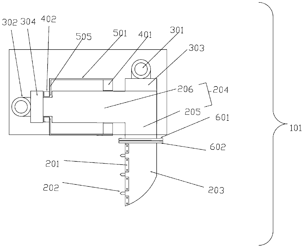
[0029] like Figure 1 to Figure 4 As shown, a cutter suction ship rock-cracking device of the present invention includes a rocker bracket 901, a rock-cracking device frame 102 is installed on the front end of the rocker bracket 901, and the rear end is hinged to the lower end of the cutter head bridge 903,

[0030] The upper end of the rocker arm support 901 and the back of the reamer head bridge 903 are connected with the rocker arm support angle adjustment hydraulic cylinder 902 for adjusting the angle of the rocker arm support 901.

[0031] The upper end of the cutter head bridge 903 is hinged with the cutter suction ship body 904, and the cutter head 905 is installed ...


PUM


Abstract

The invention discloses a rock cracking device of a cutter suction ship. The device comprises a cutter suction ship body, wherein a cutter head bridge frame is hinged to the cutter suction ship body; a rocker arm support is arranged below the cutter head bridge frame; a rock cracking device frame is arranged at the front end of the rocker arm support; the rear end of the rocker arm support is hinged to the lower end of the cutter head bridge frame; a rocker arm support angle adjusting hydraulic cylinder is connected between the upper end of the rocker arm support and the back surface of the cutter head bridge frame and used for adjusting the angle of the rocker arm support; and the top of the lower end of the cutter head bridge frame is provided with a cutter head. The device has the advantages that the rock cracking device is arranged at the front position of the cutter head on an existing cutter suction ship, transverse thrust is generated on the cutter head bridge frame due to the fact that the counter-resisting force is generated on the contact surface with the ground when the cutter head rotates in operation, and a cutter tooth arm, a rock cracking cutter or cutter teeth is driven by the rock cracking device to crush reefs by utilizing the thrust and high-frequency vibration; and the device has the advantages of high rock cracking efficiency, energy conservation, environment friendliness and the like.

Description

technical field [0001] The invention relates to the technical field of underwater rock and soil loosening, and relates to a cutter suction ship rock cracking device. Background technique [0002] At present, in the construction of underwater reef blasting projects at home and abroad, there are mainly the following ways to deal with various reefs: [0003] (1) Explode method with dynamite tree; Explosive is placed on reef surface and detonates, and its shortcoming explosive consumption is big, and efficiency is low; [0004] (2) Drilling charge blasting method: use a professional drill ship to drill holes in underwater reefs, and after drilling, put explosives into the holes and then detonate. The disadvantages are complicated operation, high construction cost, and pollution; [0005] (3) Hammering method: the heavy-duty impact hammer is lifted from the reef surface by a crane to release at a certain height, and the impact hammer freely falls to impact the reef surface and s...

Claims


Application Information

Patent Timeline
Patent Type & Authority Applications(China)
IPC IPC(8): E02F3/88E02F3/92E02F5/28
CPCE02F3/885E02F3/9231E02F5/282
Inventor 裘尧云
Owner 裘世波
Learn More