Flange disc spring, flange disc spring forming tool and forming method

A forming tooling and flanging technology, which is applied in the field of flanging disc spring forming tooling and forming, and flanging disc springs, can solve the problems that the pressure cannot be effectively adjusted, the life of the application equipment is affected, and the position of the disc spring is prone to displacement.

Pending Publication Date: 2019-09-24
LIZHOU QINGDAO HARDWARE SPRING CO LTD
View PDF0 Cites 0 Cited by
  • Summary
  • Abstract
  • Description
  • Claims
  • Application Information

AI Technical Summary

Problems solved by technology

The existing disc spring structures include conical cross-section, arc-shaped cross-section, trapezoidal cross-section, etc. Although there are differences in the use of disc springs with different cross-sectional forms, the inner and outer edges of the disc spring are flat, and the inner and outer sides of the disc spring are generally flat when installed. Due to the contact of the mating edge, there is often strong vibration in the use occasion, the position of the disc spring is prone to displacement, and the stress and fatigue of the disc spring are concentrated, which will easily cause the disc spring to break and affect the life of the application equipment. Inconsistent burrs, resulting in unstable disc spring stiffness and unable to effectively adjust pressure

Method used


Image

  • Flange disc spring, flange disc spring forming tool and forming method
  • Flange disc spring, flange disc spring forming tool and forming method
  • Flange disc spring, flange disc spring forming tool and forming method

Examples


Embodiment

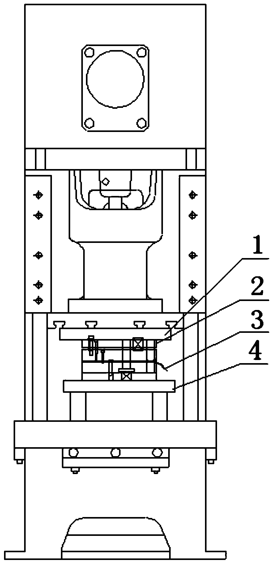
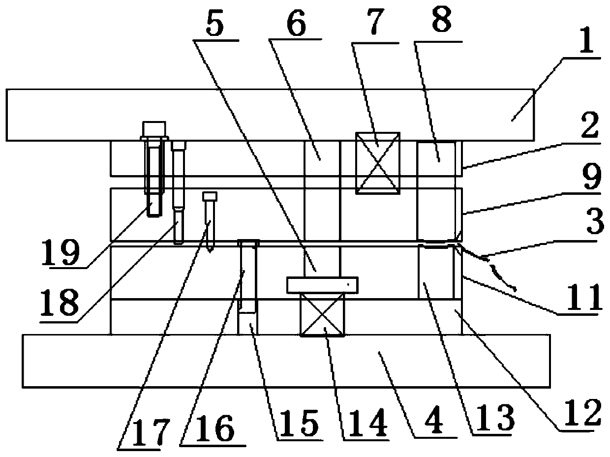
[0027] refer to Figure 1-Figure 4 , the flanging disc spring forming tooling of the present embodiment comprises an upper mold fixing plate 1, an upper template 2, a lower mold, a lower mold fixing plate 4, a pressure plate 11, and a guide plate 9, and the upper mold fixing plate 1 and the upper template 2 are welded connection, the upper template 2 and the guide plate 9 are connected up and down by screws, the lower mold fixing plate 4 is welded and connected with the lower template 12, and the upper template 2 is fixed with an inner punching die 19, a positioning punch 18, an outer punch Cutting die 6, die spring 7 and upper forming template 8, described guide plate 9 is provided with the guide through hole of corresponding inner punching die 19, positioning punch 18, outer punching die 6 and upper forming template 8, and described lower The template 12 is provided with a limit clamping shaft 16, a blanking die 5, and a lower forming template 13. The lower template 12 is pr...


PUM

PropertyMeasurementUnit
Diameteraaaaaaaaaa
Diameteraaaaaaaaaa
Heightaaaaaaaaaa

Abstract

The invention discloses a flange disc spring, a flange disc spring forming tool and a forming method. The flanging disc spring forming tool comprises an upper die fixing plate, an upper die plate, a lower die plate, a lower die fixing plate, a pressing plate and a guide plate. The upper die fixing plate is connected with the upper die plate in a welding mode. The upper die plate and the guide plate are connected up and down through screws. The lower die fixing plate is connected with the lower die plate in a welding mode. An inner blanking die, a positioning punch, an outer blanking die, a die spring and an upper forming die plate are fixed to the upper die plate. A limiting clamping shaft, a blanking female die and a lower forming die plate are arranged on the lower die plate. A spring mounting hole is formed in the lower die plate. A female die spring is arranged in the spring mounting hole, is arranged at the bottom of a blanking female die and has a blanking female die supporting and resetting effect. The blanking female die and the outer blanking die are opposite to each other up and down, and the lower forming die plate and the upper forming die plate correspond to each other up and down, so that the disc spring is formed at one time, flanging machining of the disc spring can be completed, and disc spring supporting is stable.

Description

technical field [0001] The invention belongs to the technical field of spring processing devices, and in particular relates to a flanging disc spring, a flanging disc spring forming tool and a forming method. Background technique [0002] The disc spring has the characteristics of high rigidity, small installation space, short stroke, low noise and small vibration, and is widely used in military industry, metallurgy, electric power, petrochemical, transportation and other fields. The existing disc spring structures include conical cross-section, arc-shaped cross-section, trapezoidal cross-section, etc. Although there are differences in the use of disc springs with different cross-sectional forms, the inner and outer edges of the disc spring are flat, and the inner and outer sides of the disc spring are generally flat when installed. Due to the contact of the mating edge, there is often strong vibration in the use occasion, the position of the disc spring is prone to displa...

Claims


Application Information

Patent Timeline
IPC IPC(8): B21D37/08B21D35/00
CPCB21D35/001B21D35/002B21D37/08
Inventor 范磊磊张自超仝瑞宁
Owner LIZHOU QINGDAO HARDWARE SPRING CO LTD
Why Eureka
Try Eureka