


Quick Research
Generate reliable direction feasibility study reports for your R&D in just a few steps.

Technical Q&A
Discover and master advanced knowledge NOW. Basics, ideas, possibilities, all at once.

Find Solutions
As an expert in R&D theories, this can generate solutions to your technical problems instantly.

Evaluate Feasibility
Analyze your overall solution with one click, know your potential R&D risks in advance.

Monitor Landscape
Get weekly tech updates, stay abreast of the latest tech innovations and key insights.
Spread angle measurement device, spread angle measurement method, laser device, and laser system
A measuring device and measuring method technology, applied in the field of laser systems, can solve the problems of monitoring the laser diffusion angle, difficulty, etc., and achieve the effect of a simple structure
- Summary
- Abstract
- Description
- Claims
- Application Information
AI Technical Summary
Problems solved by technology
Method used
Image

Examples
no. 1 Embodiment approach 〕
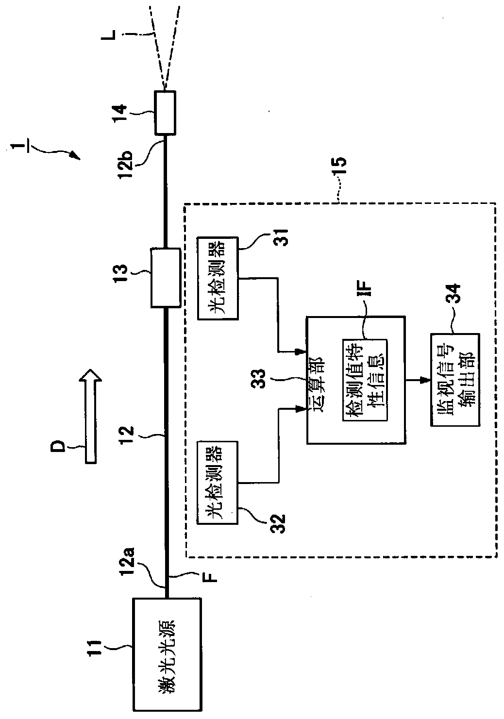
[0038] figure 1 It is a block diagram showing the configuration of the laser device of the first embodiment.
[0039] like figure 1 As shown, the laser device 1 of this embodiment includes a laser light source 11 , a transmission fiber 12 , a cladding light removing unit 13 , a connector 14 , and a spread angle measuring device 15 . The laser device 1 emits laser light L outward from the connector 14 . In addition, when the laser device 1 is used for, for example, laser processing, the laser light L is emitted from the head (not shown) at the tip of the connector 14 toward the surface to be processed.
[0040] The first end portion 12a of the transmission fiber 12 is connected to the laser light source 11, and the laser light L is input thereto. The second end 12 b of the transmission fiber 12 is connected to the connector 14 . In the present embodiment, along the propagation direction of light, the side of the first end portion 12a is referred to as the light input side, ...
no. 2 Embodiment approach 〕
[0081] Figure 7 It is a block diagram showing the configuration of the laser device of the second embodiment.
[0082] Such as Figure 7 As shown, the laser device 2 of this embodiment adopts a replacement figure 1 The shown laser device 1 has a structure in which a spread angle measuring device 15 is provided with a spread angle measuring device 40 . The diffusion angle measuring device 40 has a temperature detector 41 instead of figure 1 The configuration of the second photodetector 32 of the laser device 1 is shown.
[0083] The temperature detector 41 detects the temperature of a specific part of the cladding light removal part 13 (for example, Figure 3A , Figure 3B A detector that detects the temperature at predetermined positions of the casing 20 and the cover 25 shown). The cladding light removed by the cladding light removing unit 13 is absorbed by the cladding light removing unit 13 , thereby increasing the temperature of the cladding light removing unit 13 ....
no. 3 Embodiment approach 〕
[0086] Figure 8 It is a block diagram showing the configuration of the laser device of the third embodiment.
[0087] like Figure 8 As shown, the laser device 3 of this embodiment adopts a replacement figure 1 The shown laser device 1 has a configuration in which a diffusion angle measurement device 15 is provided with a diffusion angle measurement device 50 . In this diffusion angle measuring device 50, the configuration is omitted. figure 1 The second photodetector 32 of the shown laser device 1 inputs the detection result of the current detector CD provided in the laser light source 11 to the computing unit 33 .
[0088] The current detector CD detects the driving current supplied to the laser light source 11 (for example, the current for driving the excitation light source provided in the laser light source 11 ). The power of the laser light emitted from the laser light source 11 is approximately proportional to the driving current of the laser light source 11 . The...
PUM
 Abstract
Description
Claims
Application Information
 - R&D Engineer
- R&D Manager
- IP Professional
- Industry Leading Data Capabilities
- Powerful AI technology
- Patent DNA Extraction
Browse by: Latest US Patents, China's latest patents, Technical Efficacy Thesaurus, Application Domain, Technology Topic, Popular Technical Reports.
© 2024 PatSnap. All rights reserved.Legal|Privacy policy|Modern Slavery Act Transparency Statement|Sitemap|About US| Contact US: help@patsnap.com