Rotary leadthrough and crankshaft assembly

A technology for introducing devices and rotating components, which is applied in the field of crankshaft assemblies and internal combustion engines, and can solve problems such as large structural lengths

Active Publication Date: 2019-09-20
ROBERT BOSCH GMBH
View PDF6 Cites 0 Cited by
  • Summary
  • Abstract
  • Description
  • Claims
  • Application Information

AI Technical Summary

Problems solved by technology

However, this results in greater structural lengths in the axial direction, which correspondingly result in longer installations or machines

Method used


Image

  • Rotary leadthrough and crankshaft assembly
  • Rotary leadthrough and crankshaft assembly
  • Rotary leadthrough and crankshaft assembly

Examples


Embodiment Construction

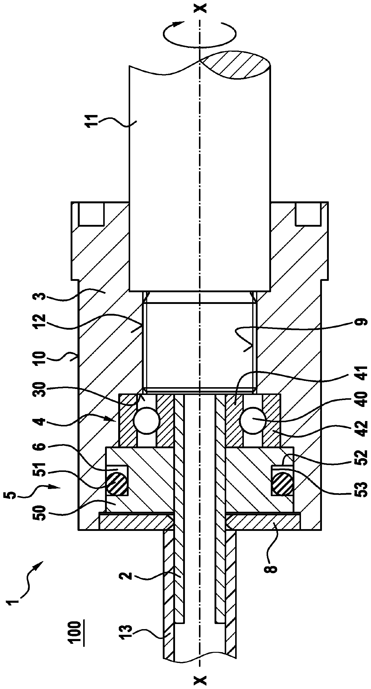
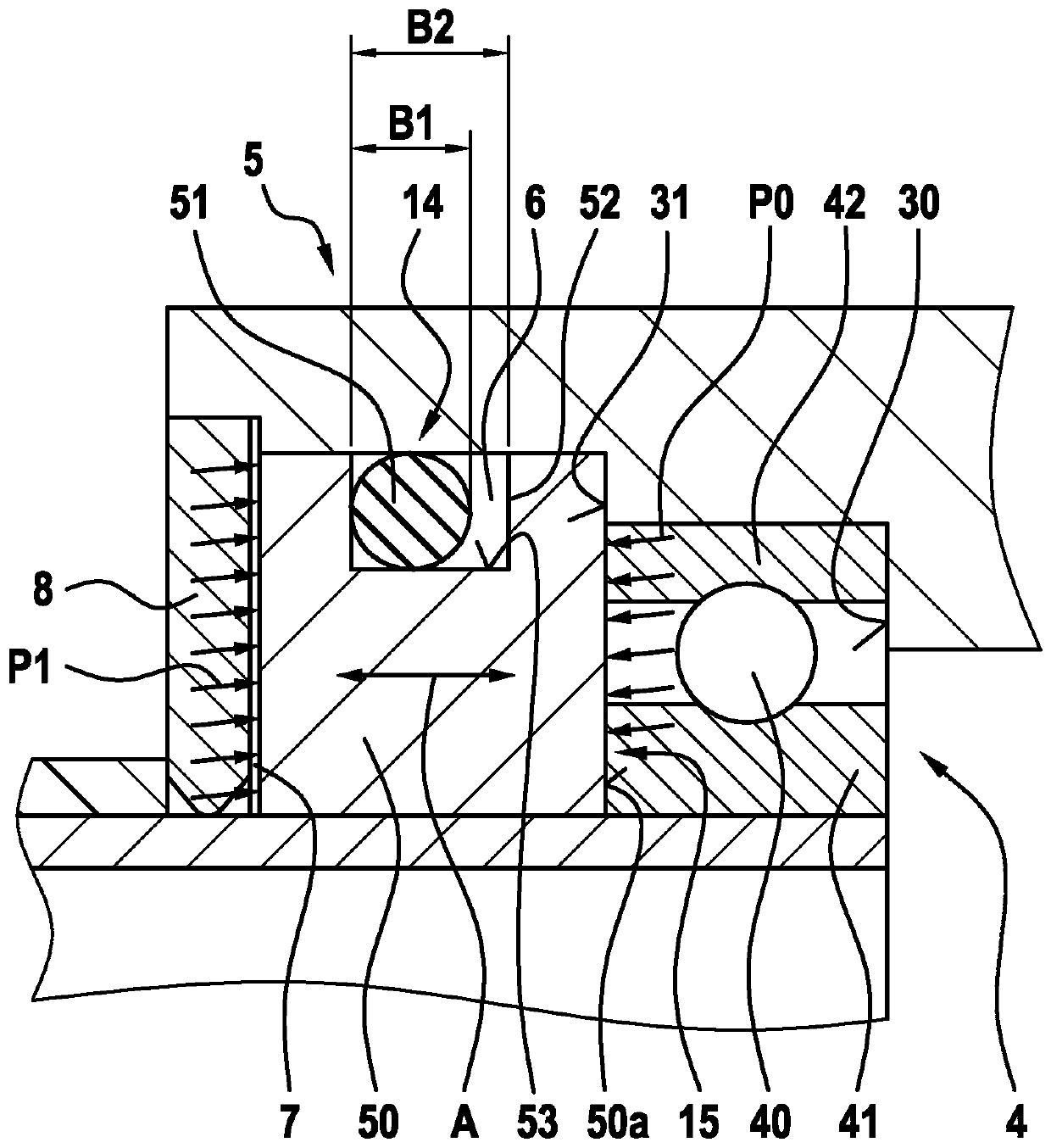
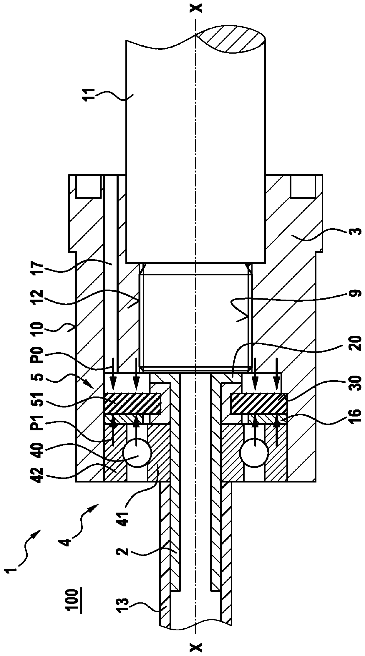
[0025] Refer below figure 1 and 2 The rotary introduction device 1 according to the first preferred embodiment of the present invention is explained in detail.

[0026] as from figure 1 It can be seen that the rotational introduction device 1 comprises a stationary member 2 and a rotating member 3 . The stationary component 2 is in this embodiment a pipe piece on which a hose 13 is arranged.

[0027] Thus, the rotating member 3 is arranged around the outer circumference of the stationary member 2 and has a notch provided in the axial direction X-X of the rotation introduction device, the notch having an internal thread 9 .

[0028] Furthermore, the rotational introduction device 1 also comprises exactly one bearing 4 , which is arranged between the stationary member 2 and the rotating member 3 .

[0029] The bearing 4 includes a plurality of rolling elements 40 , an inner bearing ring 41 and an outer bearing ring 42 . The bearing inner ring 41 is connected with the statio...


PUM


Abstract

The invention relates to a rotary leadthrough, comprising a stationary component (2), a rotating component (3), exactly one bearing (4), which supports the rotating bearing (3) on the stationary component (2), and a seal assembly (5) having a carbon ring (50) and an elastomer ring (51), wherein the carbon ring (50) is arranged between the rotating component (3) and the stationary component (2) such that the carbon ring can move in the axial direction (X-X), and wherein the seal assembly (5) has a first sealing region (14) on the elastomer ring and a second sealing region (15) on the carbon ring.

Description

technical field [0001] The present invention relates to a rotary lead-in device having a rotating member and a stationary member, a crankshaft assembly having such a rotary lead-in device, and an internal combustion engine. Background technique [0002] Different configurations of rotary introduction devices are known from the prior art, eg for transferring media from a rotating part into a stationary part or vice versa. In this case, a seal, usually achieved by spring preloading, must take place between the rotating part and the stationary part. However, this results in high friction on the seal, which significantly reduces the efficiency of the plant and machine. Furthermore, between the rotating part and the stationary part there must be a bearing arrangement, which is usually realized by the provision of two bearings. However, this results in a greater structural length in the axial direction, which results in a correspondingly longer plant or machine. SUMMARY OF THE...

Claims


Application Information

Patent Timeline
IPC IPC(8): F16J15/16F16C33/78F16J15/34F16J15/44
CPCF16C33/7886F16J15/164F16J15/3448F16J15/441F16C19/06
Inventor D·施瓦茨
Owner ROBERT BOSCH GMBH
Why Eureka
Try Eureka