Low-nitrogen premixed combustor

A premixed combustion and mixer technology, applied in burners, burners, burner ignition devices, etc., can solve the problems of high flame temperature of burners and environmental damage of nitrogen oxides, so as to reduce the production of nitrogen oxides. Effect

Pending Publication Date: 2019-09-20
关西胜和锅炉(四川)有限公司
View PDF4 Cites 0 Cited by
  • Summary
  • Abstract
  • Description
  • Claims
  • Application Information

AI Technical Summary

Problems solved by technology

[0002] The flame temperature of the traditional burner is high, and the excessive nitrogen oxides produced will cause damage to the environment. Therefore, a burner that reduces the flame temperature of the burner is urgently needed

Method used


Image

  • Low-nitrogen premixed combustor
  • Low-nitrogen premixed combustor
  • Low-nitrogen premixed combustor

Examples


Embodiment 1

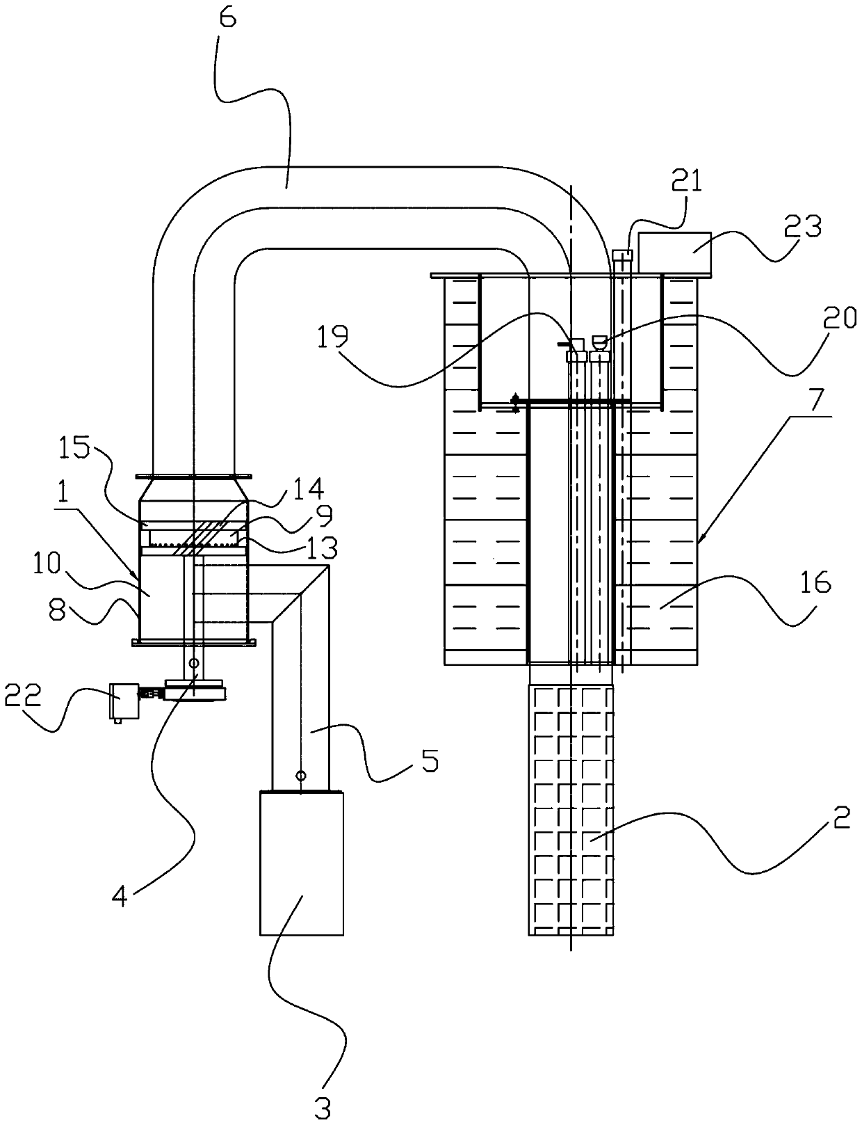
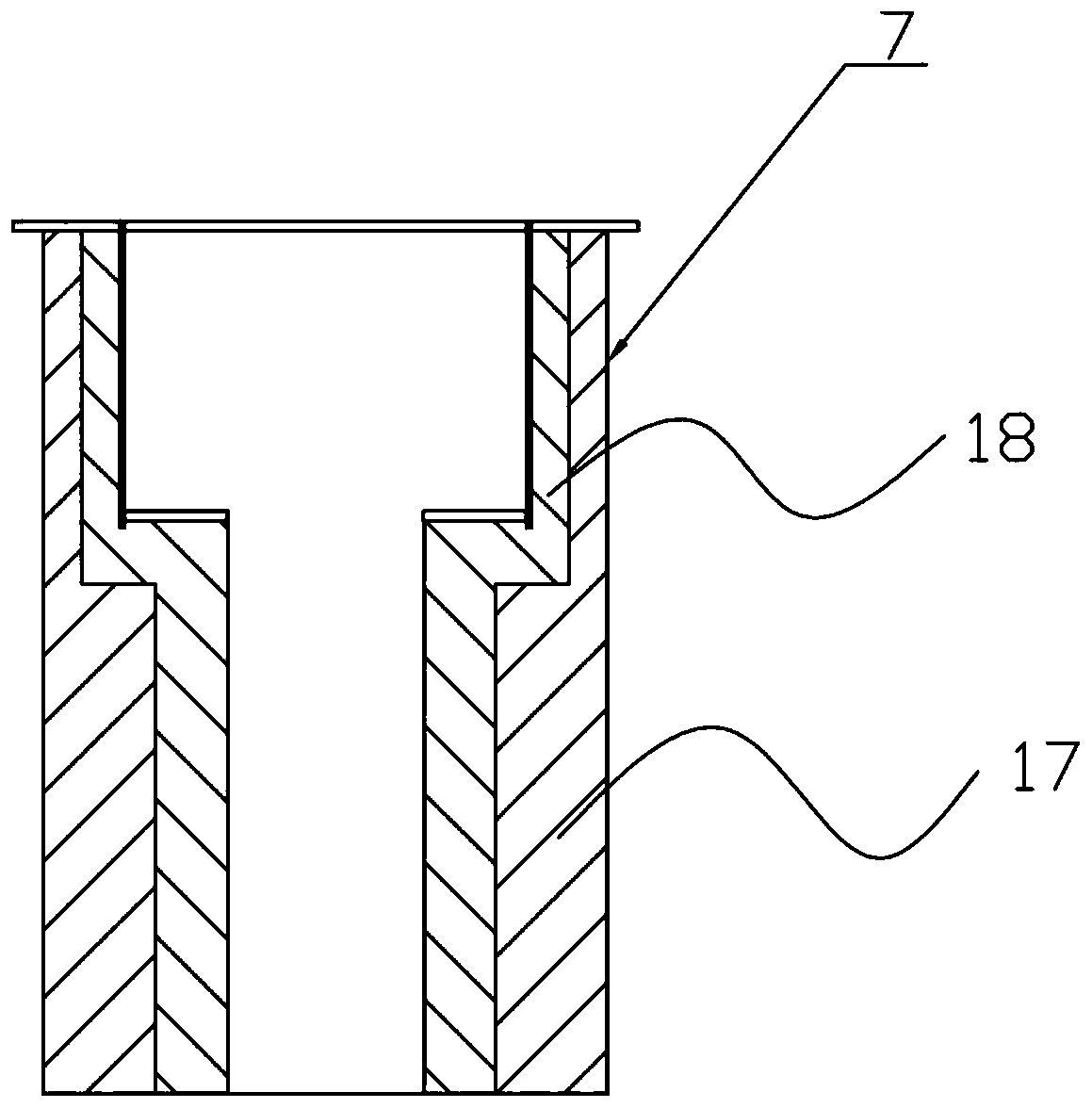
[0032] Such as Figure 1-4 As shown, a low-nitrogen premixed burner includes a mixer 1, a main combustion head 2 and a blower 3. One end of the mixer 1 is connected to a gas inlet pipe 4, and one side of the mixer 1 is fed by air. The air pipe 5 is connected to the blower 3; the other end of the mixer 1 is connected to a mixed gas delivery pipe 6, and the other end of the mixed gas delivery pipe 6 is connected to a burner body 7, and the other end of the burner body 7 Connected with the main combustion head 2;

[0033] The mixer 1 includes a housing 8, a gas outlet cylinder 9 and a mixing chamber 10, the gas outlet cylinder 9 is in the shape of a cylinder, the gas outlet cylinder 9 is provided with a gas baffle 11, and the gas inlet of the gas outlet cylinder 9 The end is connected with the gas inlet pipe 4, and a gas storage chamber 12 is formed between the gas baffle 11 and the gas inlet end of the gas outlet tube 9, and a number of gas infiltration chambers are uniformly a...

Embodiment 2

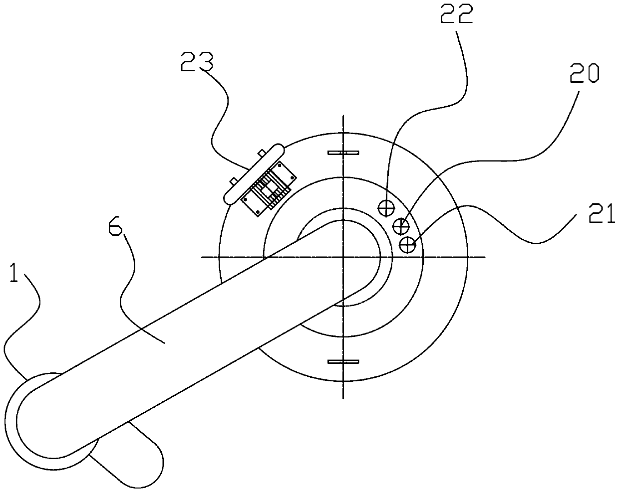
[0036] Such as figure 1 and figure 2 As shown, this embodiment is based on Embodiment 1, and a plurality of fan blades 14 are obliquely provided on the outer wall of the gas outlet cylinder 9 , and the fan blades 14 are arranged between two adjacent gas permeation holes 13 .

[0037] Several fan blades 14 are arranged obliquely on the outer wall of the gas outlet cylinder 9, and the fan blades 14 are arranged between two adjacent gas permeation holes 13, and the gas coming out of the gas permeation holes 13 is more uniformly guided by the fan blades 14. Mixed with the air entering the mixing chamber 10.

Embodiment 3

[0039] Such as figure 1 and figure 2 As shown, this embodiment is based on Embodiment 2, and the top and bottom of the fan blade 14 are provided with fixed rings 15 . The purpose of setting the fixed ring 15 on the top of the fan blade 14 is to prevent the fan blade 14 from falling off during use, which will affect the mixing accuracy during mixing.


PUM


Abstract

The invention discloses a low-nitrogen premixed combustor. The low-nitrogen premixed combustor comprises a mixer, a main combustion head and an air blower; one end of the mixer is connected with a gas inlet pipe, one side of the mixer is connected with the air blower through an air inlet pipe, the other end of the mixer is connected with a mixed gas delivery pipe, the other end of the mixed gas delivery pipe is connected with a combustor body, and the other end of the combustor body is connected with the main combustion head; the mixer comprises a shell, a gas outlet cylinder and a mixing chamber, wherein a gas baffle is arranged in the gas outlet cylinder, a gas storage chamber is formed between the gas baffle and a gas inlet end of the gas outlet cylinder, and a plurality of gas permeation holes which are uniformly distributed are formed in the side wall of the gas storage chamber; and the mixing chamber is formed between the gas outlet cylinder and a bottom cover of the shell. The low-nitrogen premixed combustor has the advantages that gas mixing is more uniform, and the phenomenon that a large number of nitrogen oxides caused by too high local temperature pollute the environment is avoided.

Description

technical field [0001] The invention relates to the technical field of burners, in particular to a low-nitrogen premixed burner. Background technique [0002] The flame temperature of the traditional burner is high, and the excessive nitrogen oxides produced will cause damage to the environment. Therefore, a burner that reduces the flame temperature of the burner is urgently needed. Contents of the invention [0003] In order to solve the problems existing in the prior art, the present invention provides a low-nitrogen premix burner, which has the advantages of making gas mixing more uniform, avoiding excessive local temperature, and producing a large amount of nitrogen oxides to pollute the environment. [0004] In order to achieve the above object, the technical solution adopted by the present invention is: a low-nitrogen premixed burner, including a mixer, a main combustion head and a blower, one end of the mixer is connected with a gas inlet pipe, and one end of the mi...

Claims


Application Information

Patent Timeline
IPC IPC(8): F23D14/02F23D14/46F23D14/62F23D14/78F23N1/00F23N5/00
CPCF23D14/02F23D14/62F23D14/46F23D14/78F23N1/007F23N5/00F23D2203/007F23D2207/00F23N2227/12
Inventor 仲野胜彦
Owner 关西胜和锅炉(四川)有限公司
Why Eureka
Try Eureka