
Mechanical linkage anti-pull anchor rod

An anti-pulling anchor and linkage technology, which is applied to the installation of bolts, electromechanical devices, electric components, etc., can solve the problems of reducing the strength and stability of rock and soil, weak bolt resistance, unfavorable anchor fixing, etc., to achieve Effects of increasing service life, lowering temperature, and improving heat dissipation efficiency

Active Publication Date: 2019-09-20
南京六合高新建设发展有限公司
View PDF7 Cites 4 Cited by
  • Summary
  • Abstract
  • Description
  • Claims
  • Application Information

AI Technical Summary

Problems solved by technology

[0003] When the anchor rod goes up and out of the tunnel and encounters soft soil at the top of the tunnel, the contact area between the anchor rod and the rock formation is small, and the anchor rod is easy to slide inside the anchor hole, so that the pull-out resistance of the anchor rod is not strong, and it is easy to fall off the anchor hole and reduce the rock formation. Soil strength and stability. It is inconvenient to inject cement slurry into the anchor hole from bottom to top to tighten the anchor and the rock-soil layer, which is not conducive to the fixing of the anchor.

Method used


Image

  • Mechanical linkage anti-pull anchor rod
  • Mechanical linkage anti-pull anchor rod
  • Mechanical linkage anti-pull anchor rod

Examples


Embodiment Construction

[0027] In order to make the technical means, creative features, goals and effects achieved by the present invention easy to understand, the present invention will be further described below in conjunction with specific embodiments.

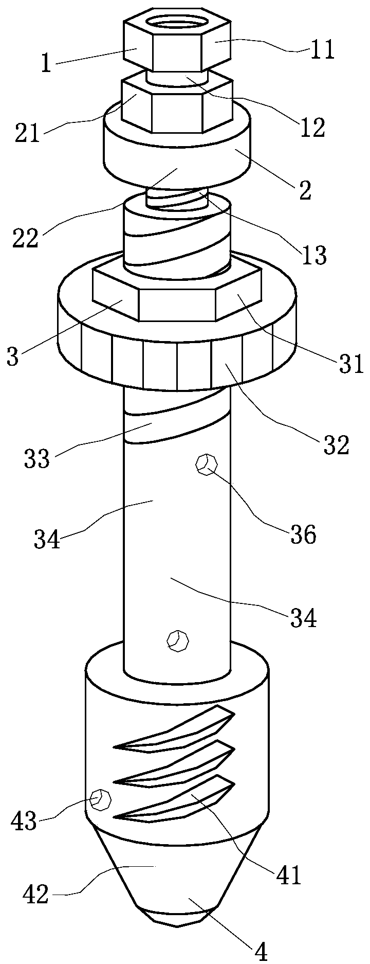
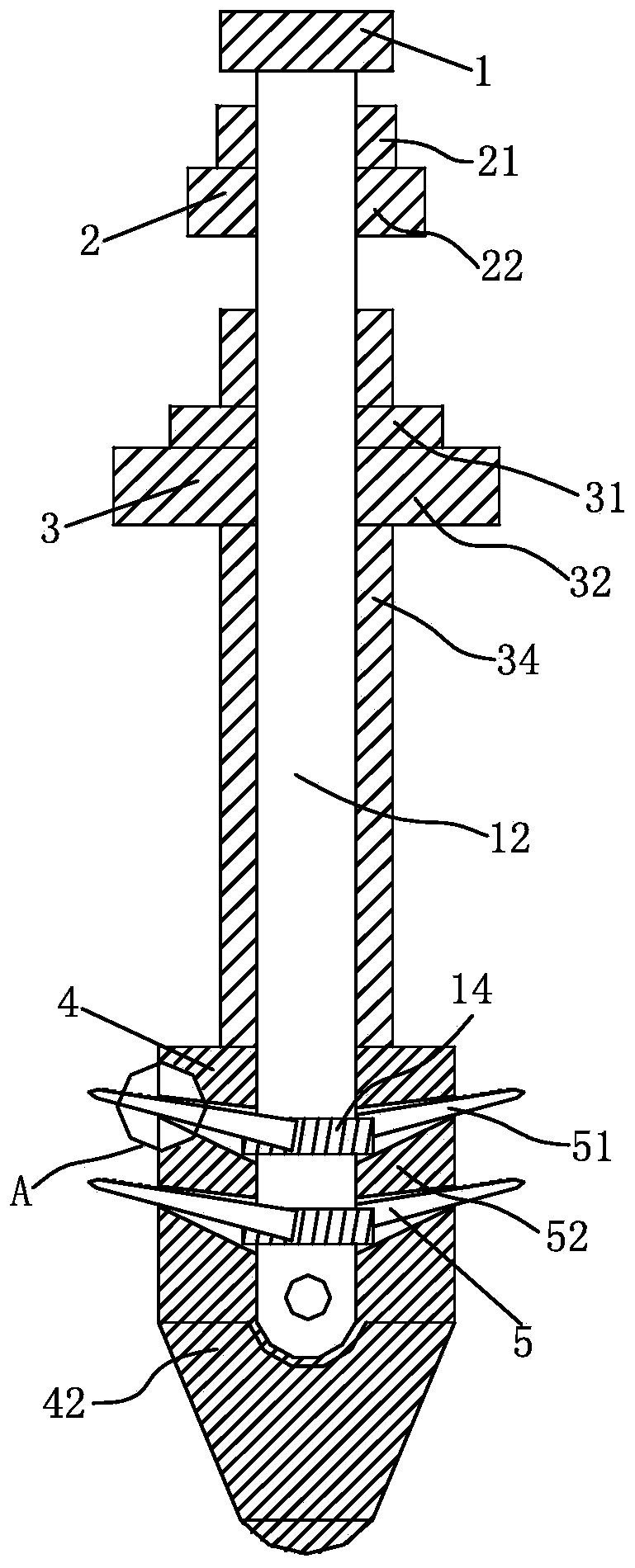
[0028] Such as Figure 1-Figure 7 As shown, a kind of mechanical linkage anti-uplift bolt according to the present invention includes a supporting structure 3, a fixed structure 4, a rotating structure 1, a fastening structure 2 and a sliding structure 5; The supporting structure 3 is rotatably connected with the rotating structure 1 for driving, the bottom end of the supporting structure 3 is equipped with the fixing structure 4 for perforation and fixing, and the rotating structure 1 is rotatably connected to the fixing structure 4 Inside, the fixed structure 4 is slidingly connected with the sliding structure 5 for inserting into rock and soil for fixing, and the sliding structure 5 is meshed and connected to the bottom end of the rotating stru...


PUM


Abstract

The invention relates to the field of anchor rods, and in particular to a mechanical linkage anti-pull anchor rod. The mechanical linkage anti-pull anchor rod comprises a printing structure, an inkjet structure, a supporting structure, a rotating structure, a fixing structure, a fastening structure and a sliding structure; in the rotating process of a fixing rod, a grouting opening close to a supporting seat firstly communicates with a first slurry outlet hole close to the supporting seat, cement slurry is injected into the first slurry outlet hole, and the fixing rod continues being rotated, so that a grouting opening located in the middle communicates with a first slurry outlet hole close to a fixing block, cement slurry is injected, and the fixing rod continues being rotated, so that a grouting opening located in the fixing block communicates with a second slurry outlet hole, cement slurry is injected, thus the cement slurry is injected into an anchor hole layer by layer from bottom to top in the process that a limiting rod enters a rock formation to increase the contact area of the anchor rod and the rock formation, after the limiting rod completely slides out of the interior of the fixing block, the contact area of the anchor rod and the rock layer is increased, and the cement slurry is injected into the anchor hole while a fixing column is firmly fixed in the anchor hole.

Description

technical field [0001] The invention relates to the field of bolts, in particular to a mechanical linkage anti-lift bolt. Background technique [0002] Anchor is the most basic part of roadway support in contemporary coal mines. It reinforces the surrounding rock of the roadway so that the surrounding rock can support itself. Now the bolt is not only used in mines, but also in engineering technology. Carry out main body reinforcement for slopes, tunnels, and dam bodies. [0003] When the bolt goes up and out of the tunnel and encounters soft soil at the top of the tunnel, the contact area between the bolt and the rock formation is small, and the bolt is easy to slide inside the anchor hole, which makes the pull-out resistance of the bolt weak, and it is easy to fall off the anchor hole and reduce the rock formation. Soil strength and stability, the anchor rod is inconvenient to inject cement slurry from bottom to top inside the anchor hole to fasten the anchor rod with the ...

Claims


Application Information

Patent Timeline
Patent Type & Authority Applications(China)
IPC IPC(8): E02D5/74E21D21/00H02K5/10H02K5/18H02K5/24H02K9/04H02K9/20
CPCE02D5/74E21D21/00H02K5/10H02K5/18H02K5/24H02K9/04H02K9/20
Inventor 不公告发明人
Owner 南京六合高新建设发展有限公司
Learn More