Workpiece dislocation grabbing method
A workpiece, reverse direction technology, applied to conveyor objects, object unstacking, object stacking and other directions, can solve the problem that the workpiece cannot complete the automatic grasping operation, etc., to achieve the effect of automatic control
- Summary
- Abstract
- Description
- Claims
- Application Information
AI Technical Summary
Problems solved by technology
Method used
Image
Examples
Embodiment 1
[0034] Workpieces are divided into single-sided types according to their shapes. When the workpieces are stacked together in positive and negative order, the central axis of the workpiece does not overlap with the central axis of the entire stack of workpieces. With the workpieces in the above stacking manner, the automatic grabbing operation of the workpieces cannot be completed.
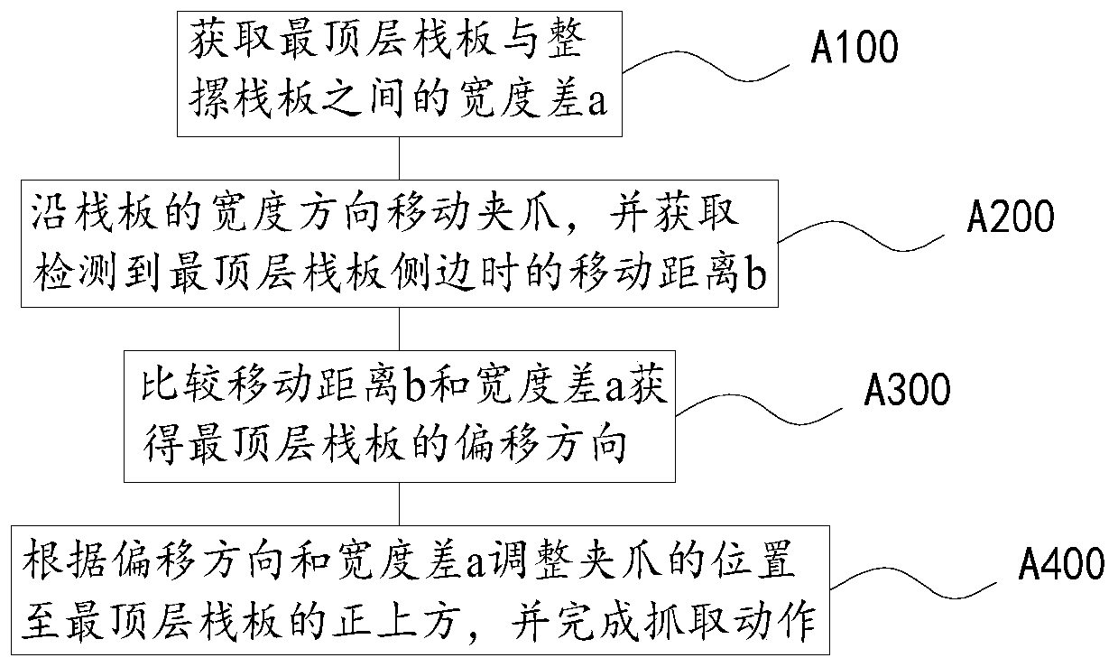
[0035] Such as figure 1 As shown, in order to solve the above problems, this embodiment proposes a workpiece misalignment grasping method, which is used for the case where the central axis of the workpiece does not overlap with the central axis of the entire stack of workpieces. The hardware includes at least two sets of initial positions and the entire stack of workpieces The central axis is the jaws whose axis is arranged symmetrically along the width direction.
[0036] Most of the workpieces are made of plates with two supporting feet. In this embodiment, the side where the supporting feet are...
Embodiment 2
[0070] Based on the workpiece misalignment grasping method described in Embodiment 1, this embodiment provides a workpiece grasping device, which is used to grasp left and right cross-stacked workpieces.
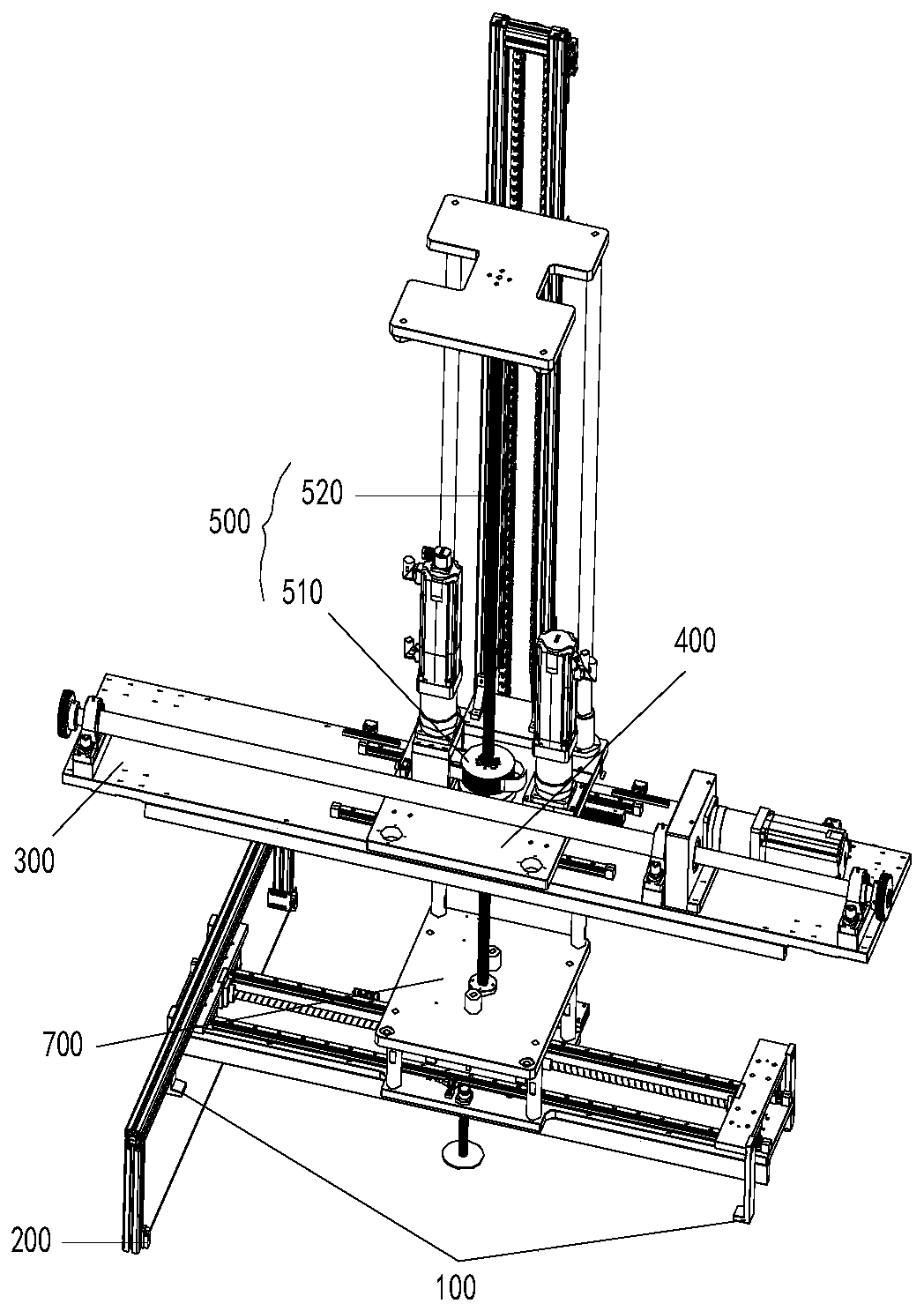
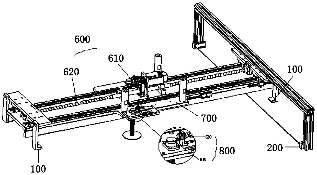
[0071] Such as Figure 2-3 As shown, its hardware structure includes, in addition to the two sets of linked jaws 100 required in the workpiece misalignment grasping method, a workpiece detection component 200 located at one of the jaws 100 and a moving distance detection component.
[0072] The workpiece detection component 200 moves synchronously with the gripper 100, and generates a trigger signal when the gripper 100 reaches the side of the topmost workpiece;
[0073] The moving distance detection component acquires the moving distance of the gripper 100 during the process from starting the workpiece detection component 200 to generating the trigger signal;
[0074] The two sets of jaws 100 are located above the entire stack of workpieces, and the initial position is sym...
Embodiment 3
[0089] This embodiment provides a workpiece grabbing device, which is used to grab left and right cross-stacked workpieces.
[0090] It also includes two sets of linked jaws 100 , a workpiece detection component 200 located at one of the jaws 100 , and a moving distance detection component.
[0091] The workpiece detection component 200 moves synchronously with the gripper jaw 100, and generates a trigger signal when the gripper jaw 100 reaches the side of the topmost workpiece; the moving distance detection component acquires the distance between the workpiece detection component 200 and the trigger signal generation process. Moving distance: two sets of jaws 100 are located above the entire stack of workpieces, and the initial position is set symmetrically along the width direction of the workpiece with the central axis of the entire stack of workpieces as the axis, and moved to the topmost workpiece according to the moving distance obtained by the moving distance detection c...
PUM
 Abstract
Description
Claims
Application Information
 - R&D
- Intellectual Property
- Life Sciences
- Materials
- Tech Scout
- Unparalleled Data Quality
- Higher Quality Content
- 60% Fewer Hallucinations
Browse by: Latest US Patents, China's latest patents, Technical Efficacy Thesaurus, Application Domain, Technology Topic, Popular Technical Reports.
© 2025 PatSnap. All rights reserved.Legal|Privacy policy|Modern Slavery Act Transparency Statement|Sitemap|About US| Contact US: help@patsnap.com


