A bending device for chip pins

A bending device and pin technology, applied in the field of chip pin bending devices, can solve the problems that the accuracy and consistency are difficult to meet the use requirements, affect the chip assembly quality, lead plating damage and other problems, so as to improve the assembly quality , Adjustable bending angle, avoid scratches or damage

Active Publication Date: 2020-08-28
SHANGHAI WORKPOWER TELECOM TECH +1
View PDF1 Cites 0 Cited by
  • Summary
  • Abstract
  • Description
  • Claims
  • Application Information

AI Technical Summary

Problems solved by technology

At present, pin bending is mostly done manually, and the accuracy and consistency are difficult to meet the requirements of use. There are also some pin bending mechanisms to solve this problem, such as the application number CN106825162A, which is a track bending mechanism to bend chip pins. This bending mechanism uses a fixed chute to control the bending angle and shape. The problem is that this method has defects in the protection of the chip and the pin plating. At the same time, during the bending process, the bending stress will be more or less transmitted to the chip through the root of the pin, causing damage to the chip, directly affecting the assembly quality of the chip, and reducing the service life. The above problems Urgently need those skilled in the art to solve

Method used


Image

  • A bending device for chip pins
  • A bending device for chip pins
  • A bending device for chip pins

Examples


Embodiment Construction

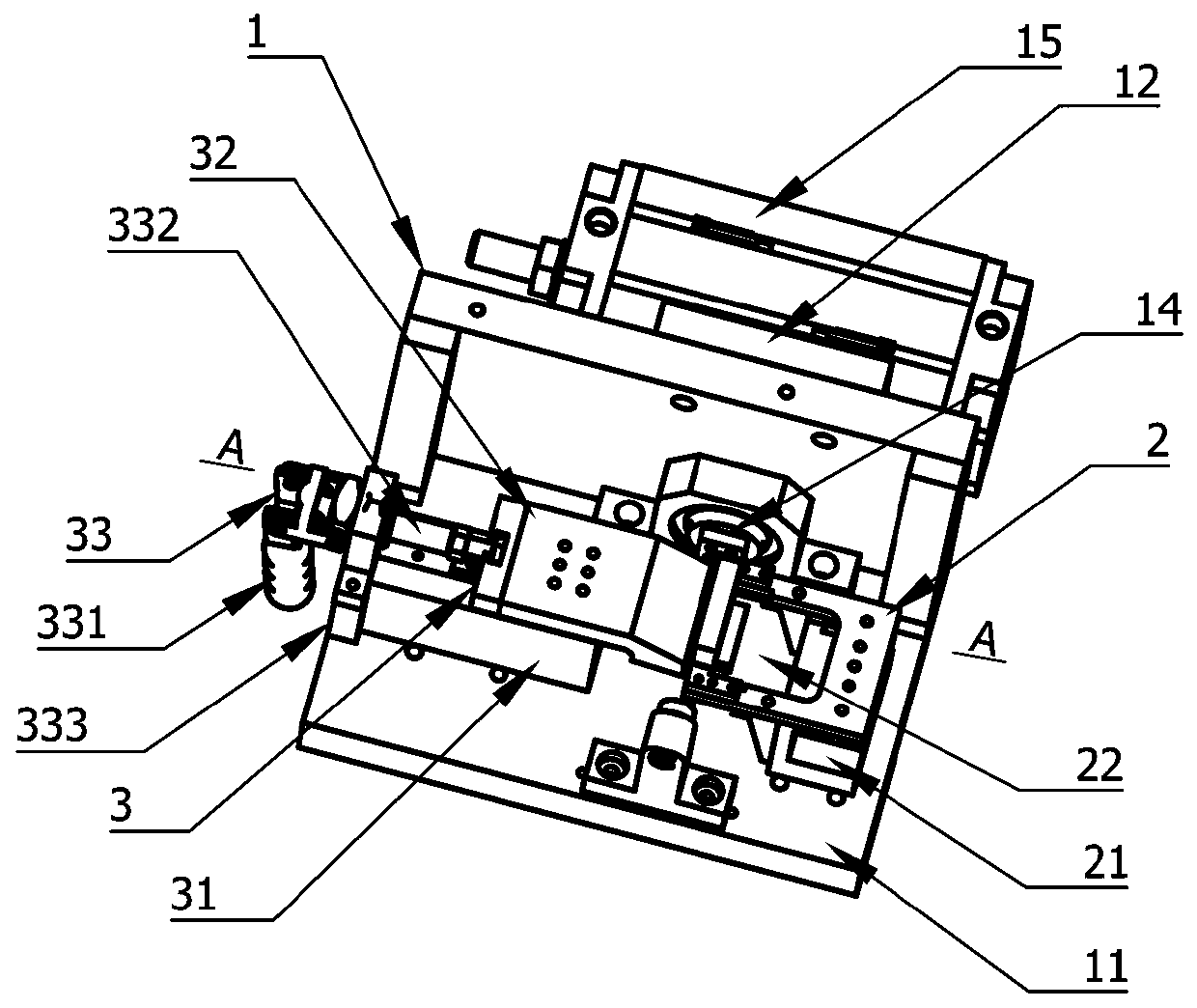
[0026] refer to figure 1 , figure 2 , the present invention includes a bending device 1, a tire frame 2 and a clamping device 3,

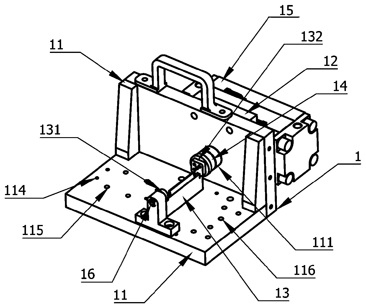
[0027] refer to figure 1 , image 3 , the bending device 1 is composed of a frame 11, a coupling 12, a bending plate 13, a main shaft 14, a rotary cylinder 15, and a secondary shaft 16; the frame 11 is arranged in an "L" shape by a base plate and a vertical plate , the main bearing seat 111 is provided on the vertical plate, the cylinder seat is provided on the outside of the vertical plate, the sub-bearing seat, the push rod seat 114, the guide rail seat 115 and the mold seat 116 are arranged on the base plate, the push rod seat 114, the guide rail The axes of the seat 115 and the tire seat 116 are collinear and the axis is parallel to the surface of the vertical plate.

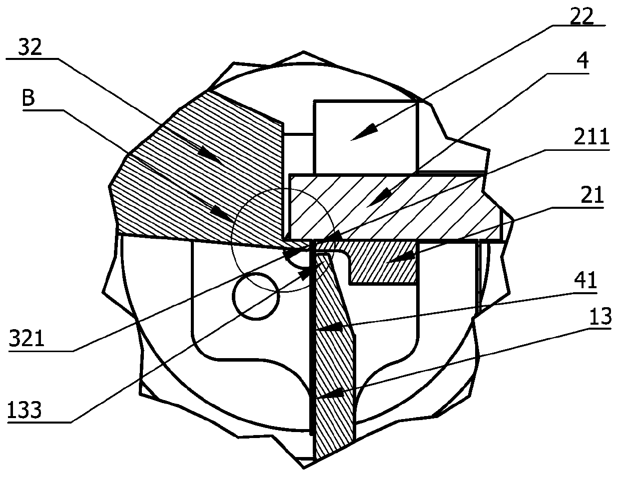
[0028] refer to figure 1 , image 3 , Figure 4 , the bent plate 13 is a plate with a shaft hole 131 at one end and a connection plate 132 at the other end;

[0029] The...


PUM


Abstract

The invention discloses a bending device of a chip pin. The bending device comprises a bending device, a jig frame and a clamping device. According to the bending device, a first clamping cutting edge is arranged on a clamping fixture of the jig frame, a second clamping cutting edge is arranged on a clamping block of the clamping device, the pins of the chips to be bent are clamped between the two cutting edges through a pushing mechanism, bending plates are driven by rotating air cylinders to be bent to the pins of the chips, the bending stress is blocked from the root of the pin to the chip in the bending process of the pin, in the bending process, the plate surface of the bending plate is in surface contact with the pin of the chip, the bending precision is high, the bending angle is adjustable, scratches or damage to the surface of the pin is completely avoided, so that the assembly quality of the chip is improved, and the service life of the chip is prolonged.

Description

technical field [0001] The invention relates to the technical field of chip assembly, in particular to a chip pin bending device. Background technique [0002] As chips are more and more widely used in high-precision equipment, the requirements for the bending quality of chip pins are getting higher and higher. At present, pin bending is mostly done manually, and the accuracy and consistency are difficult to meet the requirements of use. There are also some pin bending mechanisms to solve this problem, such as the application number CN106825162A, which is a track bending mechanism to bend chip pins. This bending mechanism uses a fixed chute to control the bending angle and shape. The problem is that this method has defects in the protection of the chip and the pin plating. At the same time, during the bending process, the bending stress will be more or less transmitted to the chip through the root of the pin, causing damage to the chip, directly affecting the assembly quali...

Claims


Application Information

Patent Timeline
Patent Type & Authority Patents(China)
IPC IPC(8): B21F1/00
CPCB21F1/00
Inventor 高伟亚张集石锦成刘林琳
Owner SHANGHAI WORKPOWER TELECOM TECH
Why Eureka
Try Eureka