A sorting sand screening machine

A technology of sand screening machine and screen mesh, applied in the field of sand screening machine, can solve the problems of adding sand material, large floor space, high height, etc., and achieve high screening efficiency, increase screening time, and increase screening efficiency. Effect

Active Publication Date: 2020-01-07
HARBIN UNIV
View PDF9 Cites 0 Cited by
  • Summary
  • Abstract
  • Description
  • Claims
  • Application Information

AI Technical Summary

Problems solved by technology

The uppermost side of the classification sand screening machine is provided with a material inlet, three sand screening boxes and three discharge platforms. The edge of the discharge platform is provided with a discharge port. The pore diameter gradually increases, and the sand screening machine and the discharge table have a 20° inclination angle compared with the base. This sorting sand screening machine can quickly classify sand with different particle sizes, reduce manual labor, and improve screening efficiency; The machine has three layers and the sand screen needs to be long to fully screen the sand. It is too high to add sand and the floor area is too large.

Method used


Image

  • A sorting sand screening machine
  • A sorting sand screening machine
  • A sorting sand screening machine

Examples


specific Embodiment approach 1

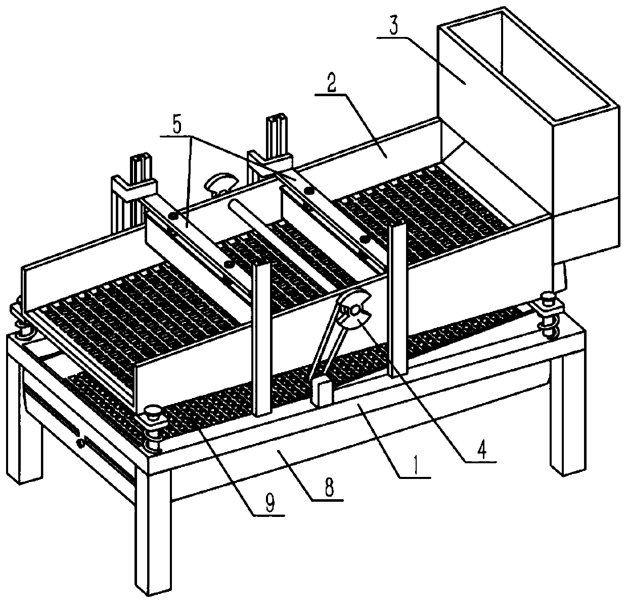
[0032] Such as Figure 1-11 As shown, a sorting sand screening machine includes a base body 1, a first screen 2, an initial collection bucket 3, an oscillation part 4, a slow-down mechanism 5, a brake part 6, a transmission part 7, a sub-bucket 8, and an increaser 9 and the rack 10, the base 1 is connected with the first screen 2, the right end of the first screen 2 is fixedly connected with the initial receiving bucket 3, and the oscillation part 4 is connected to the middle part of the upper side of the first screen 2 by rotation, and slowly falls There are two mechanisms 5, and the two slow-falling mechanisms 5 are slidingly connected to the left and right sides of the middle part of the first screen 2 respectively. Symmetrically arranged, the brake part 6 is fixed on the base body 1, the base body 1 is engaged with the left end face of the rack 10 on the right side for transmission, the transmission part 7 is fixed on the base body 1, and the brake part 6 and the transmiss...

specific Embodiment approach 2

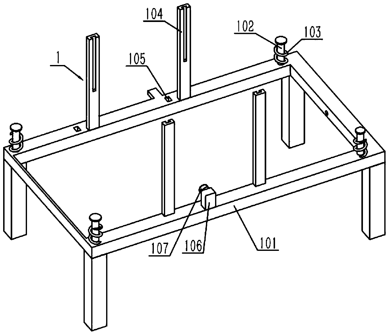
[0034] Such as Figure 1-11 As shown, the base 1 includes a base body 101, a stopper body 102, a compression spring I103, a guide rail seat 104, an opening 105, a motor I106 and a pulley I107, and four corners of the upper end of the base body 101 are respectively fixed with a stopper. Positioning bolt body 102, four limiting bolt bodies 102 are respectively covered with a compression spring I 103, the upper ends of the four limiting bolt bodies 102 are respectively fixed with a limiting block I, and the front and rear ends of the middle part of the base body 101 are fixed respectively The two guide rail seats 104, the motor I106 are fixedly connected to the base body 101, and the pulley I107 is fixedly connected to the output shaft of the motor I106. Start the motor I106, the output shaft of the motor I106 drives the pulley I107 to rotate, and the pulley I107 drives the pulley II403 to rotate through the transmission belt.

specific Embodiment approach 3

[0036] Such as Figure 1-11As shown, the first screen 2 includes a retaining frame 201, a first screen body 202 and a solid seat 203, the first screen body 202 is affixed to the retaining frame 201, and the four corners of the lower end of the retaining frame 201 are respectively One anchoring seat 203 is fixedly connected; the four anchoring seats 203 are respectively slidably connected to the four limit bolt bodies 102 , and the upper ends of the four compression springs I 103 are respectively in contact with the lower ends of the four anchoring seats 203 . Vibration promotes the sand and stones that slowly flow to the first screen body 202 to move to the left on the first screen body 202 in a layer to increase the screening efficiency. The first screen body 202 is used to separate the sand and stones, and the stones continue to the left Rolling, the sand falls through the first screen body 202 onto the second screen 901 .


PUM


Abstract

The invention relates to a sand screen, in particular to a classifying sand screen. The classifying sand screen comprises a base body, a first screen mesh, an initial collecting hopper, an oscillating part, a slow falling mechanism, a braking part, a transmission part, a dividing hopper, a shifter and a rack, wherein single-layer sand stone is conveyed to the first screen mesh through buffering and dividing the added sand stone through the initial collecting hopper in combination with vibration, so that the noise is lowered, the service life of the first screen mesh is prolonged, and the screening efficiency is increased; through the alternate lifting of two baffle plates, the single-layer sand stone is blocked in sections, the screening time is prolonged, the length of the first screen mesh is reduced, and the screening efficiency can also be increased; an arc frame and an second screen mesh swinging back and forth obliquely can increase the stroke of sand screening movement, the length of the second screen mesh is reduced, and the screening efficiency of coarse sand and fine sand can be improved; according to the classifying sand screen, the screening of stones, coarse sand and fine sand can be completed through the short screening nets and the two-layer screening structure, filling is easy due to the fact that the height is low, the occupied area of the classifying sand screen is small, and the screening efficiency is high.

Description

technical field [0001] The invention relates to a sand screening machine, more specifically a sorting sand screening machine. Background technique [0002] For example, the public number is CN207655473U, a kind of vibrating type classification sand screening machine, including base, feeding port, sand screening box, sand screening net, discharge platform, discharge port, aggregate down transmission joint, fixed frame, shaking table, Shock absorbing spring, vibration motor, etc. The uppermost side of the classification sand screening machine is provided with a material inlet, three sand screening boxes and three discharge platforms. The edge of the discharge platform is provided with a discharge port. The pore diameter gradually increases, and the sand screening machine and the discharge platform have a 20° inclination angle compared to the base. This sorting sand screening machine can quickly classify sand with different particle sizes, reduce manual labor, and improve scre...

Claims


Application Information

Patent Timeline
Patent Type & Authority Patents(China)
IPC IPC(8): B07B1/28B07B1/42B07B1/46
CPCB07B1/28B07B1/42B07B1/46B07B2201/04
Inventor 王琼马玉秋陈刚董如国
Owner HARBIN UNIV
Why Eureka
Try Eureka