
Floating type limiter

A floating, limiter technology, applied in the installation of electrical components, cables, overhead installation, etc., can solve the problems of complex structure and production process, inconvenient operation, etc., and achieve the effect of simple structure, convenient installation and convenient operation.

Pending Publication Date: 2019-09-17
GUANGZHOU PANYU CABLE WORKS
View PDF0 Cites 0 Cited by
  • Summary
  • Abstract
  • Description
  • Claims
  • Application Information

AI Technical Summary

Problems solved by technology

At present, the structure and production process of the limiter in the existing design are relatively complicated, and the operation is inconvenient

Method used


Image

  • Floating type limiter
  • Floating type limiter
  • Floating type limiter

Examples


Embodiment Construction

[0021] In order to make the object, technical solution and advantages of the present invention clearer, the present invention will be further described in detail below in conjunction with the accompanying drawings and embodiments. It should be understood that the specific embodiments described here are only used to explain the present invention, not to limit the present invention.

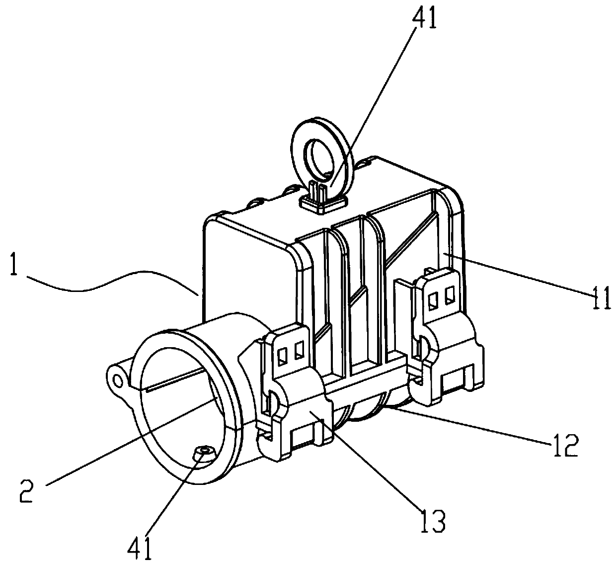
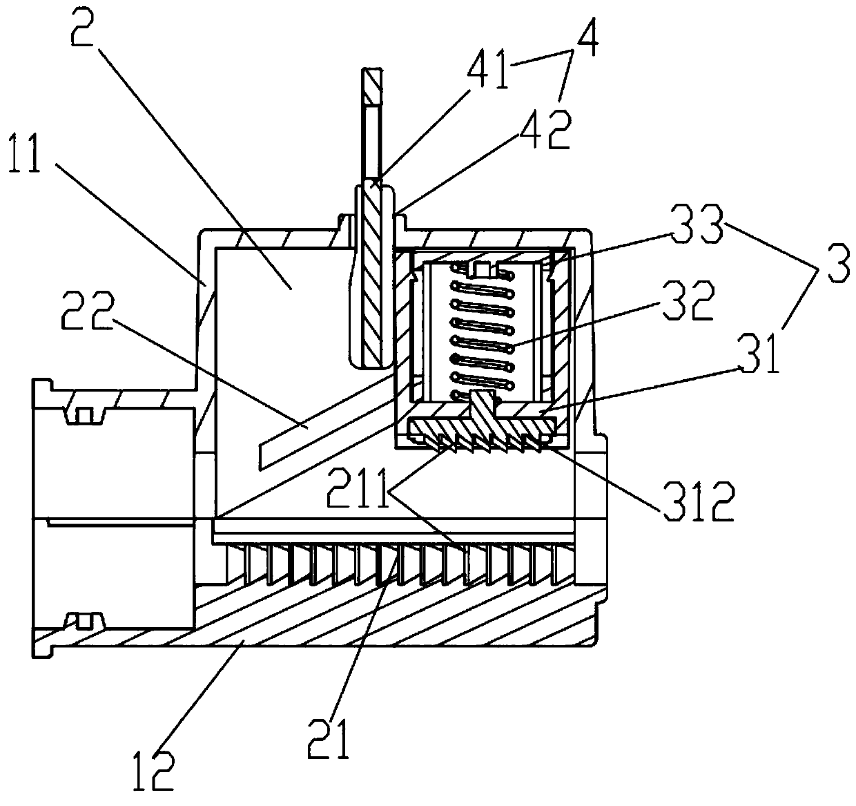
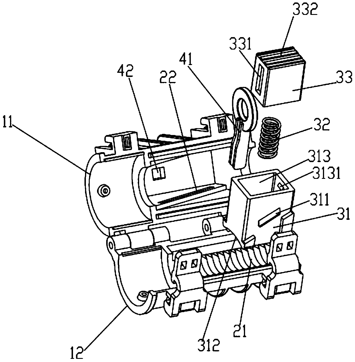
[0022] like Figure 1-3 As shown, a floating limiter 1 includes a housing. The housing includes an upper housing 11 and a lower housing 12. One side of the upper housing 11 and the lower housing 12 are hinged, and the other side is connected by a buckle 13. The connection is detachable, and the upper housing 11 and the lower housing 12 cooperate to form a wire passing chamber 2 for the cable 5 to pass through; the bottom of the wire passing chamber 2 is provided with a first clamping part 21 for placing the cable 5, and the wire passing chamber 2 is also provided with a floating crimping mechanism...


PUM


Abstract

The invention relates to the field of electric power tools, in particular to a floating type limiter. A wire passing cavity is arranged in a shell, a first wire clamping part is arranged at the bottom portion of the wire passing cavity, a floating type wire pressing mechanism is arranged in the wire passing cavity and comprises a movable pressing block, a spring and an insertion block, an inclined slideway is arranged at the side wall of the wire passing cavity, the side surface of the movable pressing block is in sliding connection with the inclined slideway, a second wire clamping part is arranged at the bottom portion of the movable pressing block, an insertion slot is arranged at the upper part of the movable pressing block, the insertion block is movably inserted into the insertion slot and movably abuts against the top of the wire passing cavity, and two ends of the spring respectively abut against the insertion block and the movable pressing block, so that the movable pressing block can be driven to slide along the inclined slideway to enable the first wire clamping part and the second wire clamping part to cooperatively clamp a cable; and the wire passing cavity is internally provided with a limiting mechanism used for limiting the movable pressing block. The floating type limiter is firm in cable limiting, convenient to operate, and simple in structure and production process.

Description

technical field [0001] The invention relates to the field of electric tools, in particular to a floating stopper. Background technique [0002] The limiter is used to limit and fix the power tool installed on the cable, and is an important part of the power tool. At present, the structure and production process of the limiter in the existing design are relatively complicated, and the operation is inconvenient. Contents of the invention [0003] In order to solve the above problems, the task of the present invention is to provide a floating limiter, which can firmly limit the position of the cable, is easy to operate, and has a relatively simple structure and production process. [0004] The task of the present invention is realized through the following technical solutions: [0005] A floating stopper, comprising a housing, the housing is provided with a wire passage cavity for cables to pass through, the bottom of the wire passage chamber is provided with a first clampi...

Claims


Application Information

Patent Timeline
IPC IPC(8): H02G7/00
CPCH02G7/00
Inventor 黄应敏胡超强尤占山邵源鹏高伟光刘金勇张仕欢王廷发冯家杰邹科敏
Owner GUANGZHOU PANYU CABLE WORKS
Learn More