Multifunctional windproof roller blind
A multi-functional, rolling shutter technology, used in door/window protection devices, shading screens, windows/doors, etc., it can solve the problems of large installation area, only full light transmission function, only full shading function, etc. Simple and convenient arrangement of wires, the effect of improving the wind resistance performance
- Summary
- Abstract
- Description
- Claims
- Application Information
AI Technical Summary
Problems solved by technology
Method used
Image
Examples
Embodiment 1
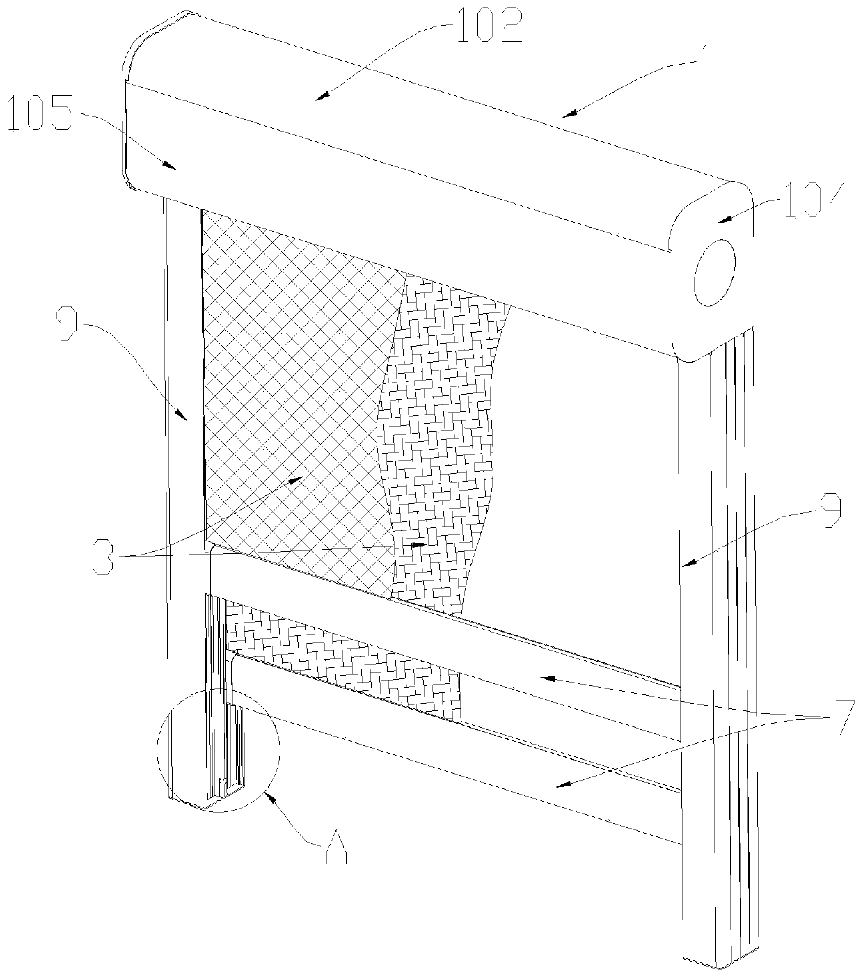
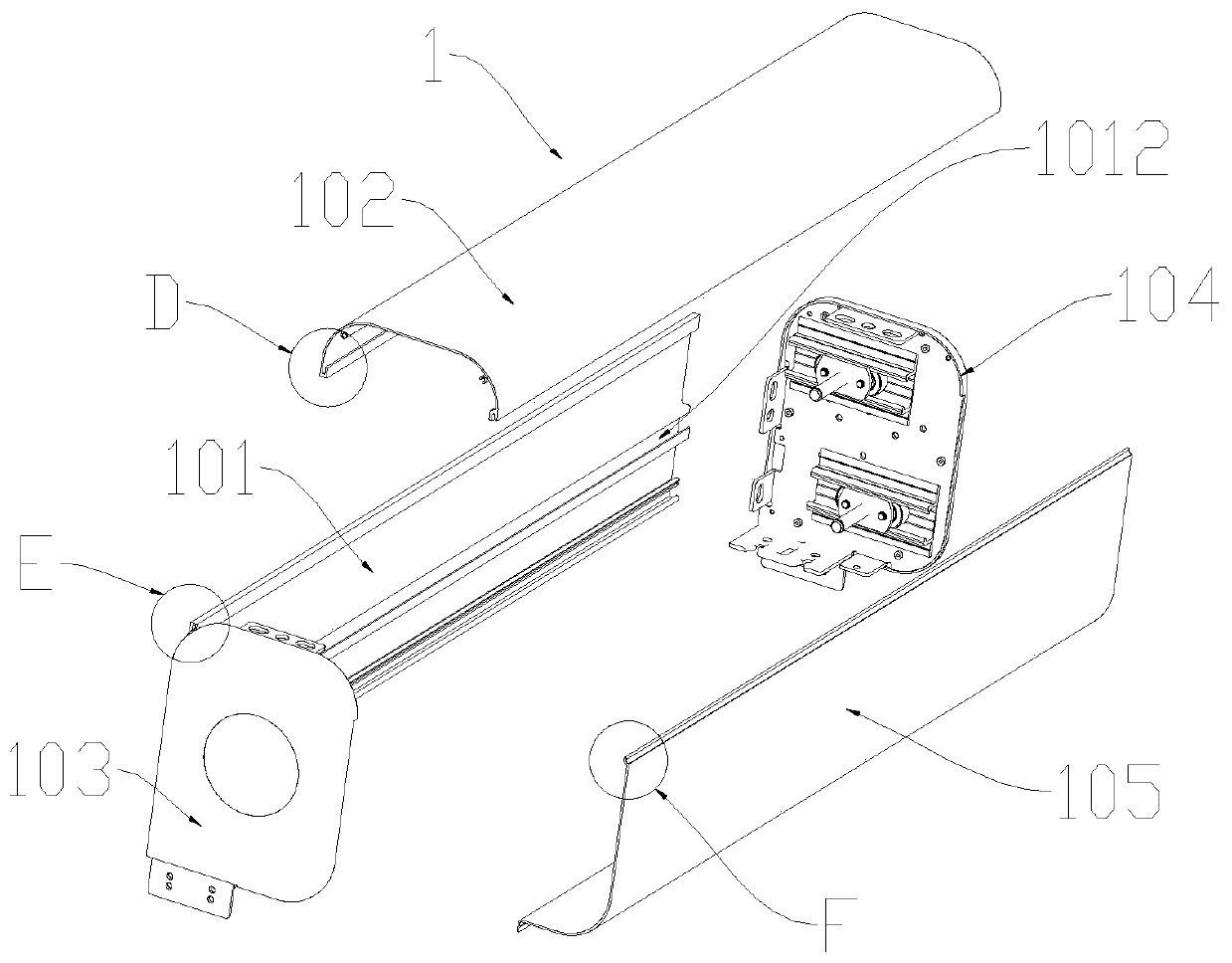
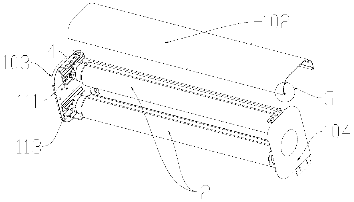
[0044] see Figure 1 to Figure 17 , a multifunctional windproof roller blind, comprising a top cover 1, a plurality of roll tubes 2, a number of fabrics 3 and a driving assembly for driving the roll tube 2 to run, and a plurality of roll tubes 2 and the drive assembly are all arranged inside the top cover 1, Specifically, see figure 2 , the top cover 1 includes a rear cover 101, a top cover 102, a left end cover 103 and a right end cover 104, the left end cover 103 and the right end cover 104 are respectively arranged on the left and right sides of the rear cover 101, and are all in contact with the top cover 102 Snap-fit connection, see image 3 , a number of roll tubes 2 are vertically dislocated and distributed on the top cover 1, and the roll tubes 2 are dislocated on the top cover 1, which can effectively reduce the internal space of the set top cover 1 and make the structure more compact. Preferably, see Figure 5 , the roll tube 2 is a hollow structure, made of al...
Embodiment 2
[0059] Since the roller blind is in the form of electric control, in the process of lowering the fabric 3, if there is an obstacle in the roller blind, the fabric 3 may not be lowered normally, and may even cause a safety accident. In the process of fabric 3, when a child stands under the roller blind or blocks the fabric 3 from being lowered due to curiosity, it is easy to cause a safety accident of pinching the child. Based on this, on the basis of embodiment 1, see figure 1 , Figure 7 , Figure 8 and Figure 9 , design the intermediate isolation part 12 on the guide assembly 9, and place the intermediate isolation part 12 between any two adjacent guide grooves 91, and set several infrared sensors 13 on the intermediate isolation part 12, and add a voice warning System (not shown in the figure) and programmable controller (not shown in the figure), wherein, drive assembly namely tubular motor 4, infrared sensor 13 and voice warning system are all connected with programmab...
Embodiment 3
[0062] This embodiment is except the following content, other is the same as embodiment 1: see Figure 18 and Figure 19 , the flexible anti-lifting component is a pull bead 15, and the pull bead 15 is connected to the left and right sides of the fabric 3 through the connecting belt 8. In the connection form, several glass beads or steel balls can be perforated to connect the glass beads or steel balls. Steel balls are connected into one pull bead 15, and then the pull bead 15 is wrapped with the connecting belt 8, and the two side ends of the connecting belt 8 are welded and glued or sewn to the two planes of the fabric 3, so that it can also be realized The purpose of anti-lifting.
PUM
 Abstract
Description
Claims
Application Information
 - R&D Engineer
- R&D Manager
- IP Professional
- Industry Leading Data Capabilities
- Powerful AI technology
- Patent DNA Extraction
Browse by: Latest US Patents, China's latest patents, Technical Efficacy Thesaurus, Application Domain, Technology Topic, Popular Technical Reports.
© 2024 PatSnap. All rights reserved.Legal|Privacy policy|Modern Slavery Act Transparency Statement|Sitemap|About US| Contact US: help@patsnap.com


