
Automatic rotating upper plate conveying device for circuit board machining and working method of the upper plate conveying device

An automatic rotation and transmission device technology, applied in the direction of printed circuit, conveyor objects, transportation and packaging, etc., can solve the problems of unable to rotate, unable to ensure the correct direction of the circuit board, and the circuit board moves and falls, etc., to achieve flexible changes , to avoid the effect of inaccurate placement

Active Publication Date: 2019-09-17
安徽天通精电新科技有限公司
View PDF6 Cites 8 Cited by
  • Summary
  • Abstract
  • Description
  • Claims
  • Application Information

AI Technical Summary

Problems solved by technology

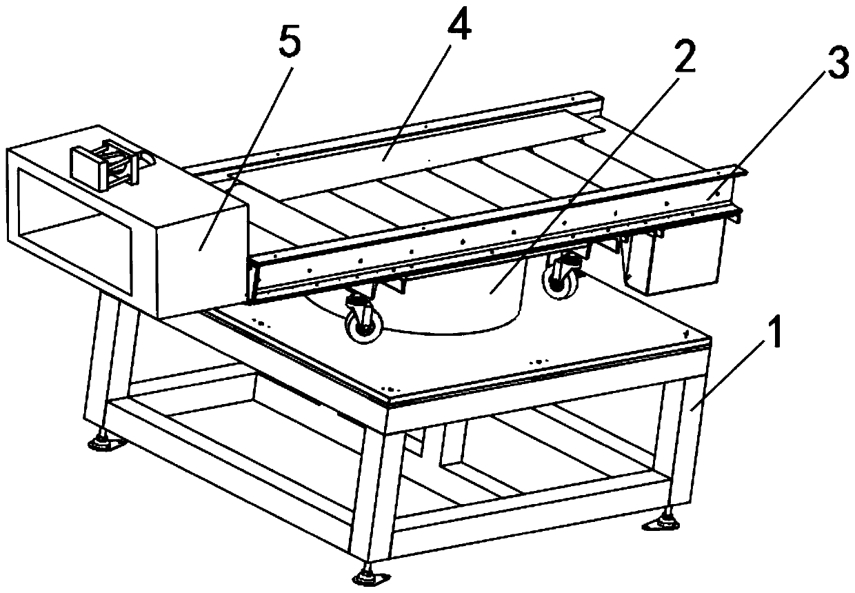
[0005] In order to overcome the above-mentioned technical problems, the object of the present invention is to provide an automatic rotating upper plate conveying device for circuit board processing, which can effectively solve the problem that the angle of the conveying frame of the existing upper plate conveying device for circuit board processing is basically fixed. It cannot be rotated; the existing board transfer device for circuit board processing is basically manually operated on the board, and it cannot be guaranteed that the circuit board will enter the conveyor frame in the correct direction when the board is loaded; the existing circuit board When the upper board transfer device for processing is transferring the circuit board, it cannot limit the position of the circuit board, which leads to the problem that the circuit board is prone to move and fall during the transfer

Method used


Image

  • Automatic rotating upper plate conveying device for circuit board machining and working method of the upper plate conveying device
  • Automatic rotating upper plate conveying device for circuit board machining and working method of the upper plate conveying device
  • Automatic rotating upper plate conveying device for circuit board machining and working method of the upper plate conveying device

Examples


Embodiment Construction

[0032] The technical solutions in the embodiments of the present invention will be clearly and completely described below in conjunction with the embodiments of the present invention. Apparently, the described embodiments are only some of the embodiments of the present invention, not all of them. Based on the embodiments of the present invention, all other embodiments obtained by persons of ordinary skill in the art without creative efforts fall within the protection scope of the present invention.

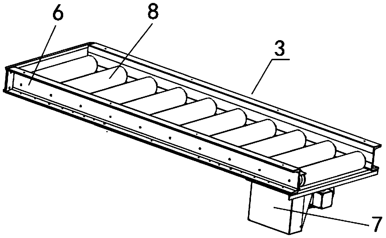
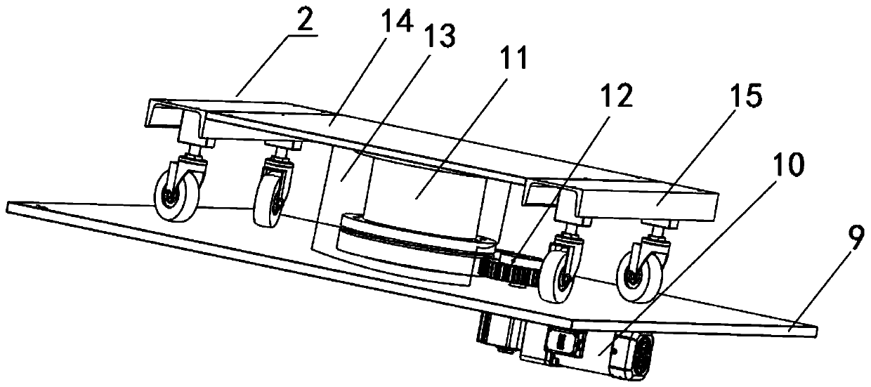
[0033] Such as Figure 1-5 As shown, an automatic rotating upper plate conveying device for circuit board processing includes a main support 1, a rotating mechanism 2 is installed on the top of the main support 1, and a transport frame 3 is installed on the top of the rotating mechanism 2, and one end of the transport frame 3 The upper plate assembly 5 is connected, and the limit assembly 4 is installed on the top of the conveying frame 3, and the rotating mechanism 2 drives the c...


PUM


Abstract

The invention discloses an automatic rotating upper plate conveying device for circuit board machining. The automatic rotating upper plate conveying device comprises a main support, a rotating mechanism is arranged at the top end of the main support, a conveying frame is arranged at the top end of the rotating mechanism, one end of the conveying frame is connected with an upper plate assembly, a limiting assembly is arranged at the top end of the conveying frame, the conveying frame comprises a fixing frame, and a plurality of groups of guide rollers are arranged on the inner side of the fixing frame. According to the upper plate conveying device and a working method, the rotating mechanism is arranged, so that the conveying frame can be driven to carry out omni-directional rotary adjustment, the angle of the conveying frame can be flexibly adjusted, so that the conveying of different directions can be met; by arranging the upper plate assembly, a circuit board can be conveniently and rapidly conveyed to the conveying frame, and the situation that a placement position is not accurate during manual plate feeding is avoided; and the limiting assembly is arranged, the conveying space of the conveying frame can be limited according to the width of the circuit board, so that the circuit board can be kept stable during conveying on the conveying frame, and deviation is avoided.

Description

technical field [0001] The invention belongs to the field of circuit board processing, and in particular relates to an upper board conveying device, in particular to an automatic rotating upper board conveying device for circuit board processing and a working method thereof. Background technique [0002] When processing circuit boards, it is necessary to use a lot of processing equipment to process them. Therefore, after each processing process is completed, it is necessary to use the upper board transfer device to transfer the circuit boards, and transfer the circuit boards to the processing equipment in the next step. for the next step of processing. [0003] The patent document with the application number of 201420218726.8 discloses a circuit board conveying device, which includes a bracket, a transmission mechanism and a gap adjusting device, which has relatively high conveying efficiency, but has a single function and relatively general use effect. [0004] There are c...

Claims


Application Information

Patent Timeline
IPC IPC(8): B65G13/06B65G13/12B65G49/06B65G47/52H05K3/00
CPCB65G13/06B65G13/12B65G47/52B65G49/06H05K3/00
Inventor 罗白强卢文广姜传明
Owner 安徽天通精电新科技有限公司
Learn More