
Heat radiation method of charging pile and circulating heat radiation structure

A technology of circulating heat dissipation and heat dissipation method, applied in charging stations, electric vehicle charging technology, electric vehicles and other directions, can solve the problems of corrosion of components, achieve high protection level, reduce heat exchange efficiency, and good dehumidification effect.

Inactive Publication Date: 2019-09-17
洛阳光法电气科技有限公司
View PDF4 Cites 9 Cited by
  • Summary
  • Abstract
  • Description
  • Claims
  • Application Information

AI Technical Summary

Problems solved by technology

The left and right convection of the air used in this heat dissipation method can easily bring the external humid environment into the interior of the charging pile, causing corrosion of the components inside the charging pile. Therefore, a new type of charging pile with high protection functions has emerged as the times require.

Method used


Image

  • Heat radiation method of charging pile and circulating heat radiation structure
  • Heat radiation method of charging pile and circulating heat radiation structure
  • Heat radiation method of charging pile and circulating heat radiation structure

Examples


Embodiment 1

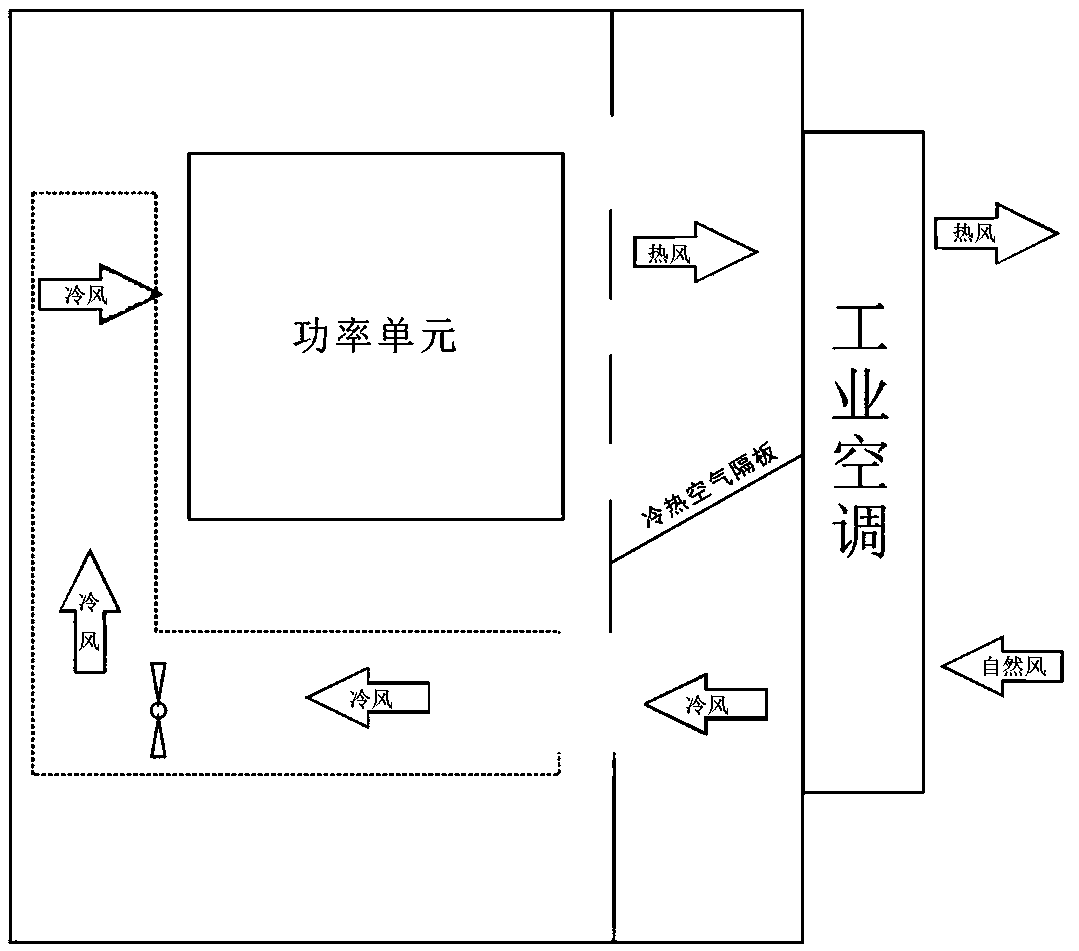
[0032] Such as figure 1 Shown: A heat dissipation method for charging piles. The interior of the charging pile cabinet is divided into a front compartment with a DC power distribution area and an AC power distribution area, and a rear compartment with a power module. The front compartment does not participate in circulating heat dissipation, and the rear compartment The warehouse is divided into two left and right chambers by the module inlet and outlet air cooling compartment and the ventilation duct compartment. The structure makes the rear warehouse form a C-shaped air duct, and the circulating air in the C-shaped air duct is used to continuously take away the heat generated by the power module, and then conducts heat exchange with the cold air generated by the industrial air conditioner to reduce the temperature of the circulating air, and the cooled circulating air is again Enter the power module through the C-shaped air duct for heat exchange. Industrial air conditioner...

Embodiment 2

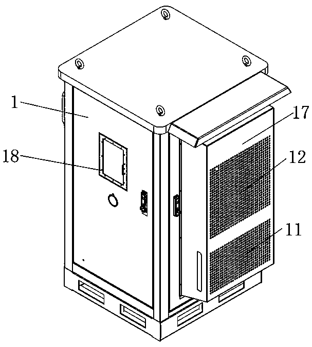
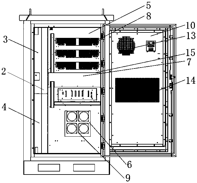
[0034] Such as Figure 2-5Shown: a heat dissipation method and circulation heat dissipation structure of a charging pile, including a cabinet body, a cabinet front door 1, and cabinet left and right doors. It is divided into a front warehouse and a rear warehouse. The front warehouse is respectively equipped with a DC power distribution area 3 and an AC power distribution area 4 from top to bottom. The DC power distribution area 3 is equipped with a control module and a metering unit. The interior of the rear compartment is divided into two chambers, left and right, by the module air inlet and outlet cooling compartment 5 and the ventilation duct compartment 6 arranged from top to bottom. The air duct dividing plate 7 of the lower chamber, the air duct dividing plate 7 is equipped with a sealing rubber strip 15, after the right side door is closed, by the extrusion of the sealing rubber strip 15, the isolation effect of the air duct dividing plate 7 is improved. Well, avoid t...


PUM


Abstract

The invention discloses a heat radiation method of a charging pile and a circulating heat radiation structure. The circulating heat radiation structure comprises a cabinet body, a cabinet front door and cabinet left and right side doors; the interior of the cabinet body is partitioned into a front bin and a rear bin through an alternating current / direct current mounting plate; the interior of the rear bin is partitioned into a left chamber and a right chamber through a module air inlet and outlet heat radiation bin and a ventilation air duct cabin which are arranged from top to bottom; an air duct partition plate used for partitioning the chamber into upper and lower chambers is arranged in the chamber, corresponding to the right side door, of the rear bin; an industrial air conditioner is arranged on the right side door of the cabinet; and the industrial air conditioner comprises an internal circulating area and an external circulating area which are isolated from each other. According to the heat radiation method of the charging pile and the circulating heat radiation structure, by using the industrial air conditioner, heat in the charging pile is radiated by using a circulating heat radiation mode so that outside air does not participate in the air circulation in the charging pile; and therefore, it is guaranteed that the interior of the charging pile is always in an environment with humidity of 70% or below, the heat in the charging pile is radiated, and the service life of a component in the charging pile is prolonged.

Description

technical field [0001] The invention relates to the technical field of electric vehicle charging, in particular to a heat dissipation method and a circulation heat dissipation structure of a charging pile. Background technique [0002] With the widespread promotion of electric vehicles, when people use electric vehicles, due to the continuous loss of power, charging them has become the most important operation, and the charging equipment derived from this has also become an indispensable supporting facility. The most common charging equipment is the charging pile, and the charging pile will emit a lot of heat during operation, which will cause accelerated aging of the components inside the charging pile and insufficient charging. [0003] The current heat dissipation method of electric vehicle charging piles is generally the direct ventilation heat dissipation method, that is, through the chassis fan, the cold air outside the cabinet enters the inside of the cabinet, and the...

Claims


Application Information

Patent Timeline
IPC IPC(8): B60L53/302B60L53/31
CPCB60L53/302B60L53/31Y02T10/70Y02T10/7072Y02T90/12
Inventor 赵星朱朝堃陈东辉
Owner 洛阳光法电气科技有限公司
Learn More