A tooling device and its use

A technology of tooling and ejecting device, applied in the direction of manufacturing tools, hand-held tools, etc., can solve the problems of time-consuming, difficult installation and disassembly, etc., and achieve the effect of reducing the difficulty of installation and disassembly, convenient transportation, and light structure

Active Publication Date: 2021-08-31
MCC BAOSTEEL TECH SERVICE
View PDF0 Cites 0 Cited by
  • Summary
  • Abstract
  • Description
  • Claims
  • Application Information

AI Technical Summary

Problems solved by technology

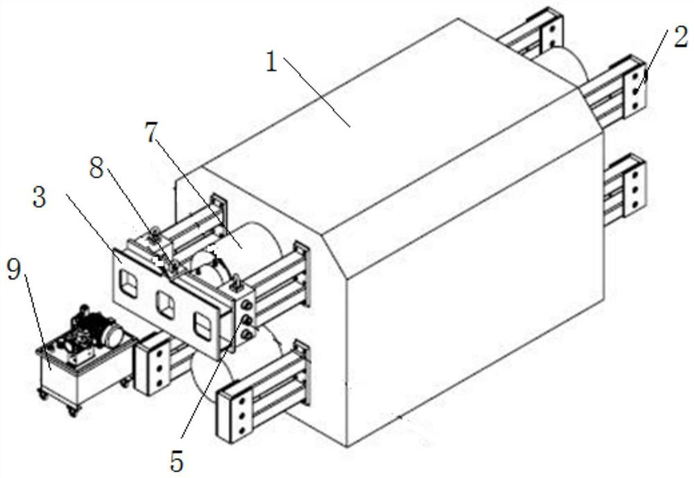
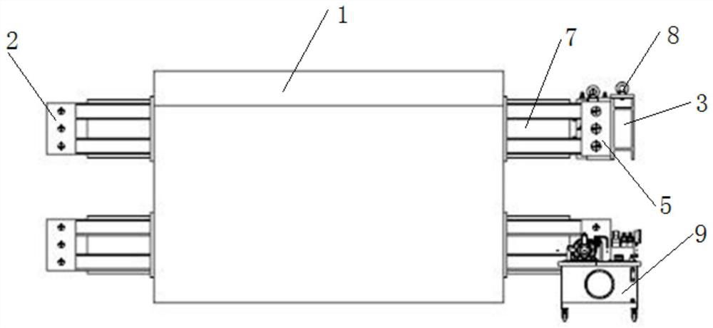
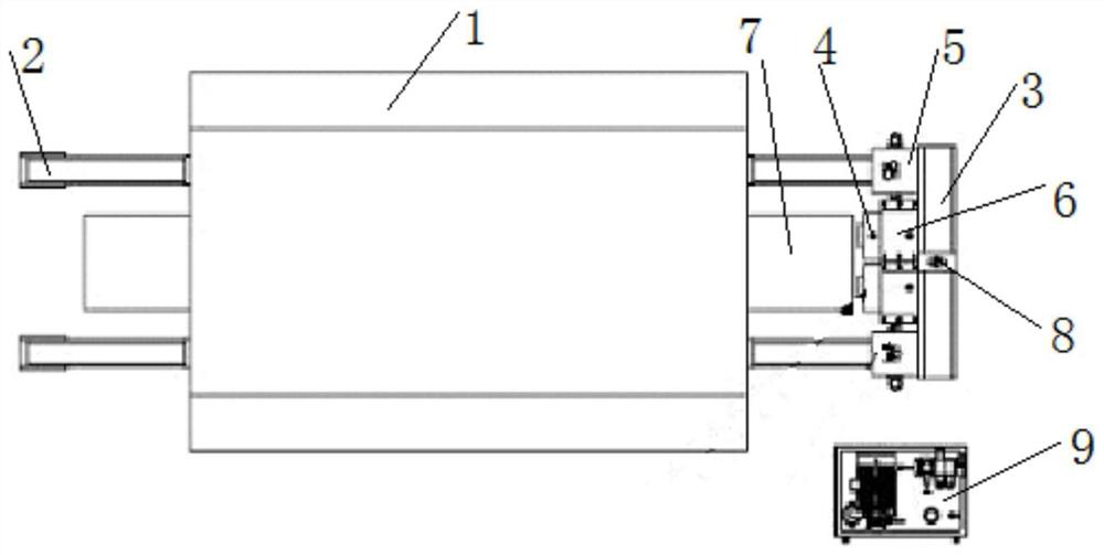
[0003] The object of the present invention is to provide a tooling device and its use. Through the detachable structure, it solves the problem that the installation and disassembly of the integral tooling device is difficult and takes a lot of time.

Method used


Image

  • A tooling device and its use
  • A tooling device and its use
  • A tooling device and its use

Examples


Embodiment Construction

[0033] The following will clearly and completely describe the technical solutions in the embodiments of the present invention with reference to the accompanying drawings in the embodiments of the present invention. Obviously, the described embodiments are only some, not all, embodiments of the present invention. Based on the embodiments of the present invention, all other embodiments obtained by persons of ordinary skill in the art without creative efforts fall within the protection scope of the present invention.

[0034] In describing the present invention, it is understood that the terms "opening", "upper", "lower", "thickness", "top", "middle", "length", "inner", "surrounding" etc. Indicating orientation or positional relationship is only for the convenience of describing the present invention and simplifying the description, and does not indicate or imply that the components or elements referred to must have a specific orientation, be constructed and operated in a specific...


PUM


Abstract

The invention discloses a tooling device and its application, and relates to the technical field of process equipment. A tooling device according to the present invention comprises: a frame on which at least one through hole is formed; and a plurality of legs fixed on the two end faces of the frame along the extending direction of the through hole, wherein all the legs on one end face The outriggers are connected to the main equipment; at least one base, the base is vertically installed on the end faces of the two outriggers on the side of the frame away from the main equipment; at least one ejector device is fixedly installed on the On the base, the telescopic rod of the ejecting device is aligned with the through hole, and the telescopic rod is allowed to be extended or shortened in the through hole. Through the detachable structure, the present invention solves the problem that the installation and disassembly of the integral tooling device is difficult and consumes a lot of time.

Description

technical field [0001] The invention belongs to the technical field of process equipment, and in particular relates to a tooling device and its application. Background technique [0002] In the field of iron and steel manufacturing, the hydraulic cylinder of the rolling mill is fixed on the rolling mill frame by bolts. Due to the large contact surface between the outer surface of the hydraulic cylinder and the hole in the frame, its adhesion is very strong. When replacing the hydraulic cylinder, it is very difficult to take out the hydraulic cylinder from the rolling mill, and it must be realized by means of a special tooling device. For the overall frame type tooling device, every time the hydraulic cylinder is replaced, the tooling device must be installed on the rolling mill archway first, and then the hydraulic cylinder is ejected from the rolling mill archway by using the hydraulic jack. Because this frock device is a monolithic structure, it is very difficult to insta...

Claims


Application Information

Patent Timeline
Patent Type & Authority Patents(China)
IPC IPC(8): B25B27/14
CPCB25B27/14
Inventor 任晓杰董辉赵夏荣
Owner MCC BAOSTEEL TECH SERVICE
Why Eureka
Try Eureka