
Steam generating device and steam cooking equipment using same

A technology of steam generating device and cooking equipment, which is applied in the field of steam cooking equipment and steam generating device, and can solve the problems of waiting for a long time and taking a long time

Pending Publication Date: 2019-09-17
VATTI CORP LTD
View PDF0 Cites 0 Cited by
  • Summary
  • Abstract
  • Description
  • Claims
  • Application Information

AI Technical Summary

Problems solved by technology

[0004] In view of this, in order to solve the problem that the existing steam generator takes a long time to generate steam, a steam generating device capable of quickly generating steam is provided
[0005] Another object of the present invention is to provide a steam cooking device using the above-mentioned steam generating device, so as to solve the problem that the existing steam cooking device needs to wait for a long time during the cooking process to produce steam

Method used


Image

  • Steam generating device and steam cooking equipment using same
  • Steam generating device and steam cooking equipment using same
  • Steam generating device and steam cooking equipment using same

Examples


Embodiment 1

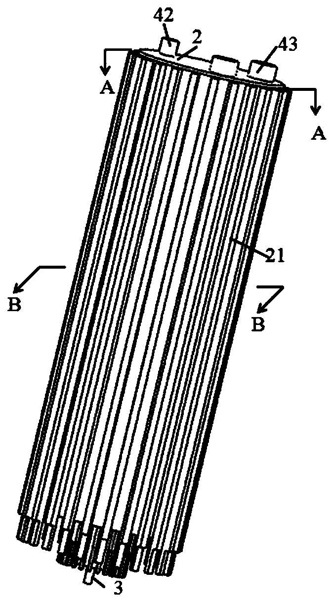
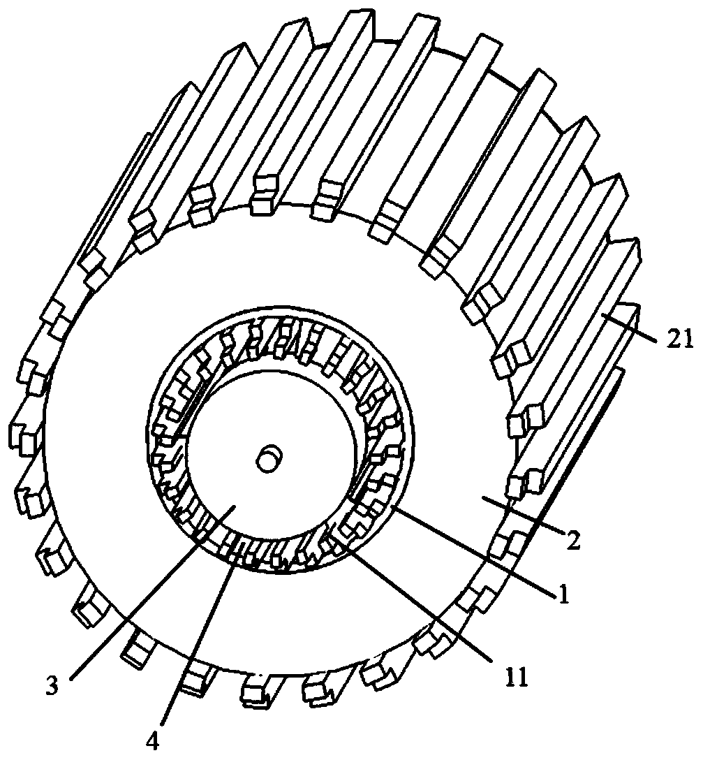
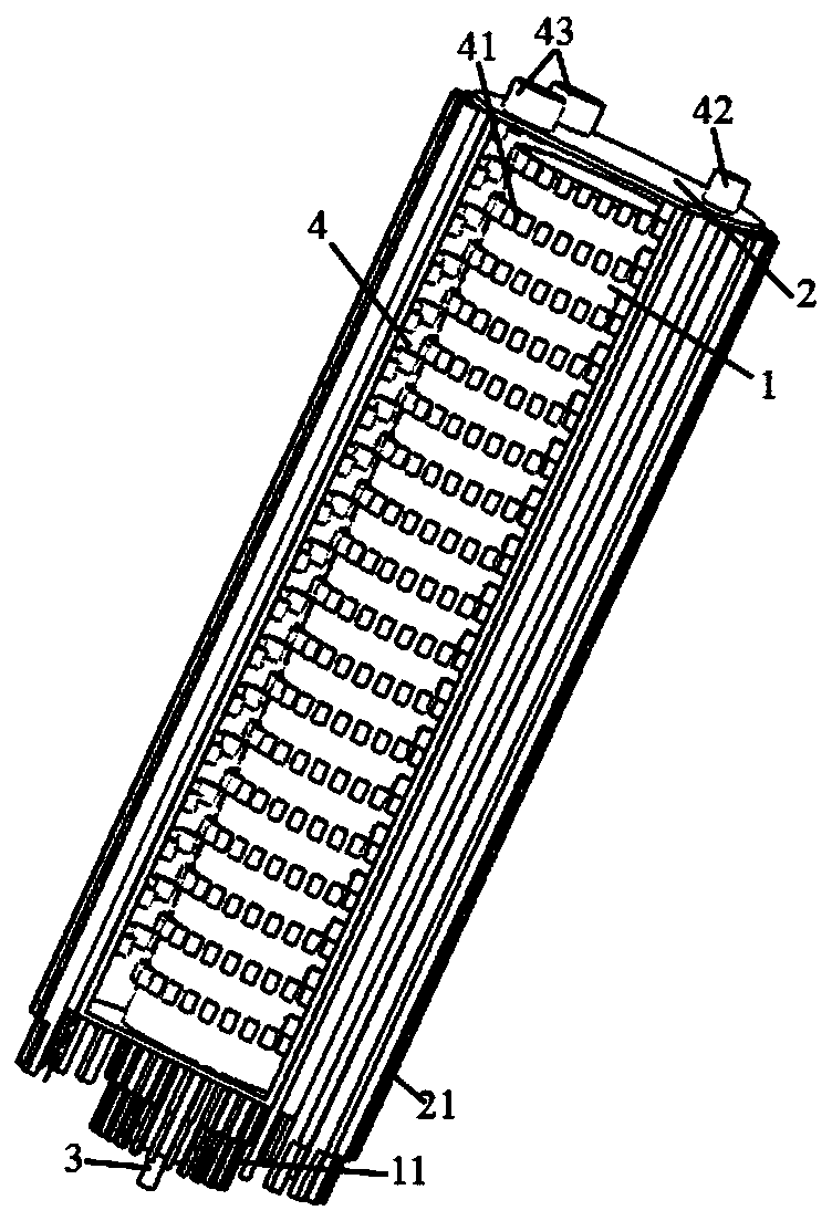
[0030] This embodiment provides a steam generating device, such as Figure 1-Figure 6 As shown, it includes a vertically arranged heating inner cylinder 1, a vertically arranged heating outer cylinder 2, a drive assembly 3 and an annular cylindrical water storage chamber 4 for generating steam;

[0031] The heating inner cylinder 1 is arranged in the heating outer cylinder 2, and the cavity formed between the heating inner cylinder 1 and the heating outer cylinder 2 is a water storage chamber 4. The drum 2 rotates with a drive assembly 2 .

[0032] Because the heating inner cylinder 1 and the heating outer cylinder 2 are arranged vertically, and the cavity formed between the heating inner cylinder 1 and the heating outer cylinder 2 is the water storage chamber 4, the water entering the water storage chamber 4 will Under the action of gravity, it flows to the bottom of the water storage chamber 4; because both the heating inner cylinder 1 and the heating outer cylinder 2 can h...

Embodiment 2

[0052] This embodiment also provides a steam cooking device using Embodiment 1, such as Figure 7 As shown, it includes a steam cooking device body 5, and the steam generating device communicates with the steam cooking device body 5;

[0053] Because the steam cooking equipment adopts the steam generating device of embodiment 1, and the steam generating device of embodiment 1 takes less time to generate steam compared with the existing steam generator, the steam generating device of embodiment 1 is used When the steam cooking equipment steams food, it can solve the problem that the existing steam cooking equipment needs to wait for a long time in the process of steaming food.

[0054] The working process of the steam cooking equipment of the present embodiment is:

[0055] Start the steam cooking equipment of this embodiment, water flows into the water storage chamber 4 from the water inlet 42, and the driving assembly 3 (motor) starts running at the same time, the driving as...


PUM


Abstract

The invention belongs to the technical field of steam generators, and discloses a steam generating device. The steam generating device comprises a heating inner cylinder, a heating outer cylinder, a driving assembly and an annular columnar water storage chamber for generating steam, wherein the heating inner cylinder and heating outer cylinder are vertically arranged; the heating inner cylinder is arranged in the heating outer cylinder, a cavity formed between the heating inner cylinder and the heating outer cylinder is the water storage chamber, and the lower end of the heating inner cylinder is provided with the driving assembly capable of driving the heating inner cylinder to rotate relative to the heating outer cylinder. The invention also discloses steam cooking equipment applying the steam generating device. The steam generating device can rapidly generate steam, and the time required by steam generation is shortened; and the steam cooking equipment solves the problem that an existing steam cooking device needs to wait for a long time in the process of cooking food.

Description

technical field [0001] The invention belongs to the technical field of steam generators, and in particular relates to a steam generator and steam cooking equipment using the steam generator. Background technique [0002] Existing domestic steam cooking devices, such as steam boilers, steam ovens, etc., their steam generators are usually divided into built-in steam generators and external steam generators according to the different setting positions. Among them, the built-in steam generator is arranged on the bottom wall of the cooking cavity of the cooking equipment, and the water in the steam generator is directly heated to generate steam; the external steam generator is arranged on the bottom wall of the cooking equipment. The outer wall of the cooking cavity is used to continuously transport the steam generated by the steam generator into the cooking cavity through the steam guide tube for cooking food. [0003] Whether it is a built-in steam generator or an external ste...

Claims


Application Information

Patent Timeline
Patent Type & Authority Applications(China)
IPC IPC(8): A47J27/04A47J36/00A47J36/24
CPCA47J27/04A47J36/00A47J36/2483A47J2027/043
Inventor 韩君庆潘叶江
Owner VATTI CORP LTD
Learn More