
Street tree planting hole structure and construction method thereof

A construction method and technology for planting holes, which are applied in the fields of botanical equipment and methods, container cultivation, gardening, etc., can solve the problems that the topsoil layer is easy to harden, fall off, and affect the infiltration of surface water, so as to improve the survival rate and reduce the maintenance cost. Effect

Pending Publication Date: 2019-09-13
GUANGDONG MEIJING LANDSCAPE CONSTR
View PDF8 Cites 11 Cited by
  • Summary
  • Abstract
  • Description
  • Claims
  • Application Information

AI Technical Summary

Problems solved by technology

This kind of tree hole has a single structure, and the air permeability of the tree root system is poor. In areas with poor soil infiltration, the tree hole is prone to water shortage; whether it is watering irrigation or natural rainfall, the topsoil layer of the tree hole is easy to harden, which affects the infiltration of surface water. It is difficult for the deep soil to effectively store water during the rainy season and watering period. Therefore, it cannot rely on its own stored water to support the growth of street trees in the dry season and when watering is delayed. The survival rate of street tree planting is related to the air permeability around the planting soil ball.
The traditional planting holes cannot meet the above requirements, which leads to yellow leaves, falling off, slow growth, and tree death in serious cases during the growth of street trees.

Method used


Image

  • Street tree planting hole structure and construction method thereof

Examples


Embodiment Construction

[0028] The implementation of the present invention will be described in detail below in conjunction with the accompanying drawings. The accompanying drawings are only for reference and description, and do not constitute a limitation to the protection scope of the present invention.

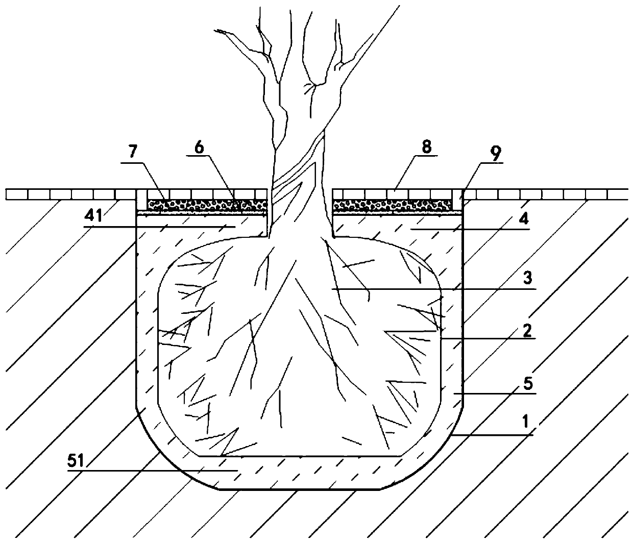
[0029] Such as figure 1 As shown, on the one hand, the present embodiment provides a street tree planting hole structure, in which a planting soil ball 3 wrapped with a water-permeable geotextile bag 2 is embedded in the planting hole 1, and the outer surface of the planting soil ball 3 and the inner surface of the planting hole 1 The upper peripheral aquifer 4 and the lower peripheral aquifer 5 are filled therebetween, the upper peripheral aquifer 4 and the lower peripheral aquifer 5 respectively include a top aquifer 41 and a bottom aquifer 51, and the water purification layer 6 is located at On the upper end surface of the top water storage layer 41, the permeable layer 7 is located on the uppe...


PUM

PropertyMeasurementUnit
Thicknessaaaaaaaaaa
Thicknessaaaaaaaaaa
Thicknessaaaaaaaaaa

Abstract

The invention provides a street tree planting hole structure and a construction method thereof. The street tree planting hole structure is characterized in that a planting soil ball wrapped with a permeable geotextile bag is arranged in a planting hole, space between the outer surface of the planting soil ball and the inner surface of the planting hole is filled with an upper peripheral water storage layer and a lower peripheral water storage layer, the upper peripheral water storage layer comprises a top water storage layer, the lower peripheral water storage layer comprises a bottom water storage layer, a water purification layer is located on the upper end surface of the top water storage layer, a permeable layer is located on the upper end surface of the water purification layer, a permeable brick layer is located on the upper end surface of the permeable layer, and side stone is arranged on the peripheries of the permeable brick layer and the permeable layer. According to the planting hole structure and the construction method, water infiltration and storage can be facilitated, and a root microreservoir is formed; not only is overland runoff in the rain season adjusted, but also a water supplementing function in the dry season is exerted, the water storage structure can also guarantee ventilation of roots of street trees, the planting hole is endowed with functions of storing rainwater in rainy days and releasing stored water to support street tree growth in sunny days, the maintenance cost is reduced, and urban rainwater is recycled.

Description

technical field [0001] The invention relates to the technical field of street tree planting holes, in particular to a street tree planting hole structure and a construction method thereof. Background technique [0002] Street trees are an important part of urban landscaping landscape, and the growth of street trees plays an important role in the landscape effect of urban roads. Most of the street tree planting is to use artificial or mechanical to take soil from the ground below the surface to form a tree hole, and then backfill the original soil dug out before the seedlings are planted. This kind of tree hole has a single structure, and the air permeability of the tree root system is poor. In areas with poor soil infiltration, the tree hole is prone to water shortage; whether it is watering irrigation or natural rainfall, the topsoil layer of the tree hole is easy to harden, which affects the infiltration of surface water. It is difficult for the deep soil to effectively s...

Claims


Application Information

Patent Timeline
IPC IPC(8): A01G9/02A01G29/00
CPCA01G9/02A01G29/00
Inventor 王光娜黄思敏关振鹏周韵怡江敏辉郭瑞卿
Owner GUANGDONG MEIJING LANDSCAPE CONSTR
Learn More