
Cable core stranding machine

A stranding machine and wire core technology, which is applied in the direction of cable/conductor manufacturing, electrical components, circuits, etc., can solve the problems that the wire core is not easy to tighten, affects the cable qualification rate, and the wire core is loosely twisted.

Active Publication Date: 2019-09-10
宝胜(宁夏)线缆科技有限公司
View PDF8 Cites 5 Cited by
  • Summary
  • Abstract
  • Description
  • Claims
  • Application Information

AI Technical Summary

Problems solved by technology

[0006] The present invention can solve the problem that in the existing stranding process, the wire core is usually wound on the reel and then set on the sleeve. Fast wire outlet may cause the core drum to still rotate for a period of time when the wire core stops feeding out, so that the wire core will be looser when twisted later, which is not conducive to the twisting of the wire core, and the pulled out wire core is relatively tight during the twisting process. Long, the wire core part pulled out under the action of gravity is not easy to tighten, which affects the pass rate of the twisted cable and other problems

Method used


Image

  • Cable core stranding machine
  • Cable core stranding machine
  • Cable core stranding machine

Examples


Embodiment Construction

[0037] Embodiments of the present invention will be described below with reference to the drawings. In the process, in order to ensure the clarity and convenience of illustration, we may exaggerate the width of the lines or the size of the constituent elements in the diagram.

[0038] In addition, the following terms are defined based on the functions in the present invention, and may be different according to the user's or operator's intention or practice. Therefore, these terms are defined based on the entire content of this specification.

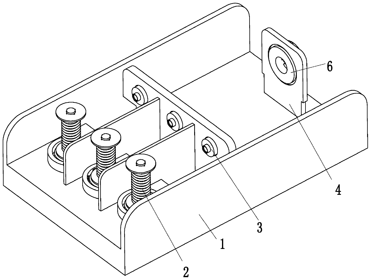
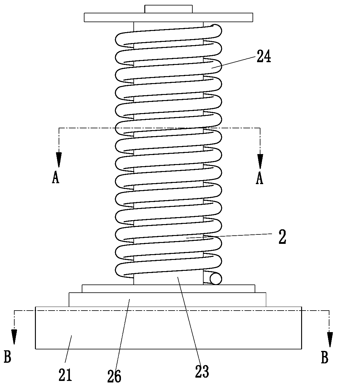
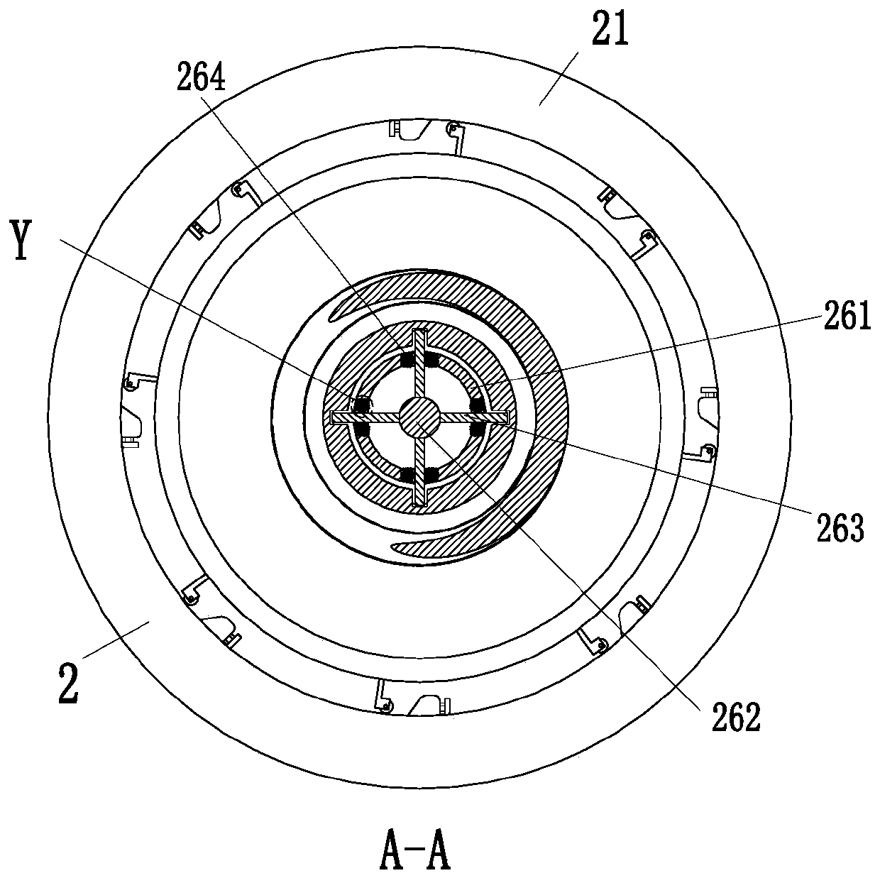
[0039] like Figure 1 to Figure 9 As shown, a cable core stranding machine includes a shelf base 1, an anti-loose reel 2, an anti-loose discharge barrel 3, a support plate 4, an electric turntable 5 and a limit device 6, and the spacer The front end of the base 1 is evenly equipped with an anti-loose reel 2, and the middle part of the base 1 is evenly equipped with an anti-loose discharge cylinder 3, and each anti-loose reel 2 is corre...


PUM


Abstract

The invention relates to a cable core stranding machine which comprises a partition base, anti-loosening spools, anti-loosening discharge cylinders, a support plate, an electric rotating disc and a limiting device, wherein the anti-loosening spools are uniformly mounted at the front end of the partition base; the anti-loosening discharge cylinders are uniformly mounted in the middle of the partition base; each anti-loosening spool corresponds to one anti-loosening discharge cylinder; the support plate is mounted at the rear end of the partition base; the electric rotating disc is mounted in the support plate; and the limiting device is arranged on the electric rotating disc. The stranding machine can solve the problems that a core is usually wound on the spools and then sleeved on a sleevein the existing stranding process, the spools rotate along with pulling of the core by the stranding machine during stranding, outgoing of the core on the spools is relatively quick to result in rotation of the core spools for some time after outgoing stop of the core, core stranding is relatively loosen and adverse, the pulled core is relatively long during the stranding, and the core pulled under gravity action is difficult to tighten.

Description

technical field [0001] The invention relates to the field of cable stranding, in particular to a cable core stranding machine. Background technique [0002] Cable is a general term for items such as optical cables and cables. There are many uses of cables, mainly used for multiple functions such as control installation, connection equipment, and power transmission. It is a common and indispensable thing in daily life. Stranding is performed in a stranding machine, but the following problems often exist in the existing stranding process: [0003] 1. During the stranding process, the wire core is usually wound on the reel and set on the sleeve. When twisting, the reel will rotate with the stranding machine pulling the wire core. The wire core reel still rotates for a period of time when the wire core stops coming out, so that the wire core is looser when twisted later, which is not conducive to the twisting of the wire core; [0004] 2. During the twisting process, since th...

Claims


Application Information

Patent Timeline
Patent Type & Authority Applications(China)
IPC IPC(8): H01B13/02
CPCH01B13/02H01B13/0207
Inventor 郭公升许旭闫宇
Owner 宝胜(宁夏)线缆科技有限公司
Learn More