


Quick Research
Generate reliable direction feasibility study reports for your R&D in just a few steps.

Technical Q&A
Discover and master advanced knowledge NOW. Basics, ideas, possibilities, all at once.

Find Solutions
As an expert in R&D theories, this can generate solutions to your technical problems instantly.

Evaluate Feasibility
Analyze your overall solution with one click, know your potential R&D risks in advance.

Monitor Landscape
Get weekly tech updates, stay abreast of the latest tech innovations and key insights.
Ejector tube and cooker ejector containing same
A technology of ejector and ejector tube, which is applied in the direction of burners, household appliances, household stoves/stoves, etc., which can solve the problems of poor air ejection ability and achieve the effect of improving the ejection effect and increasing the inner wall area
- Summary
- Abstract
- Description
- Claims
- Application Information
AI Technical Summary
Problems solved by technology
Method used
Image

Examples
Embodiment 1
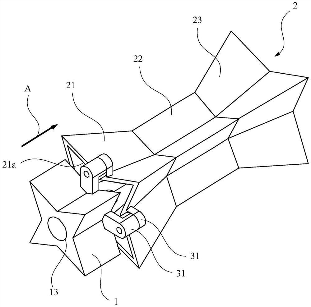
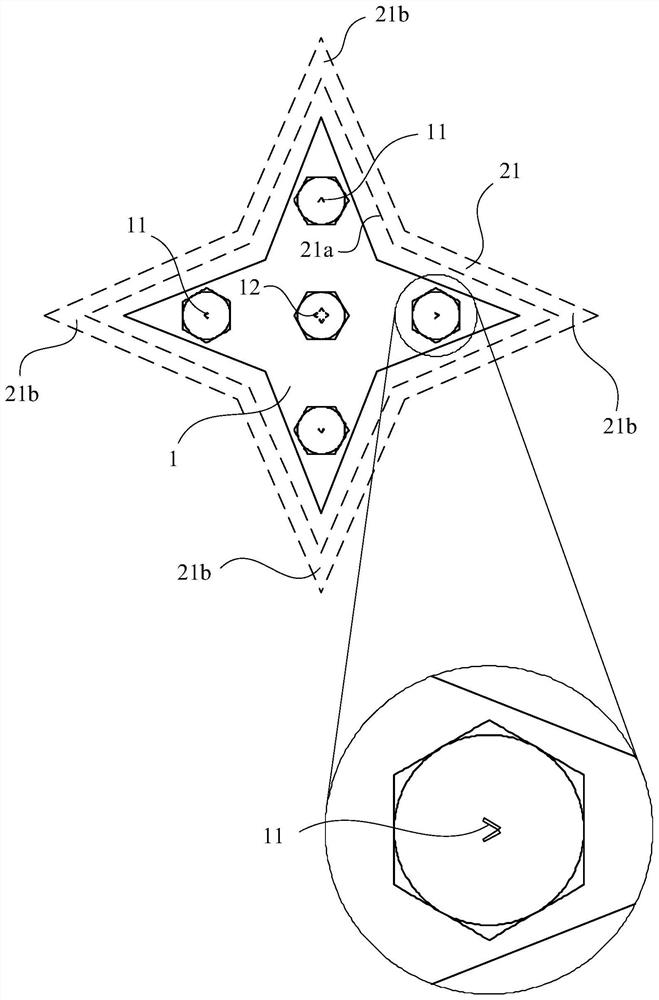
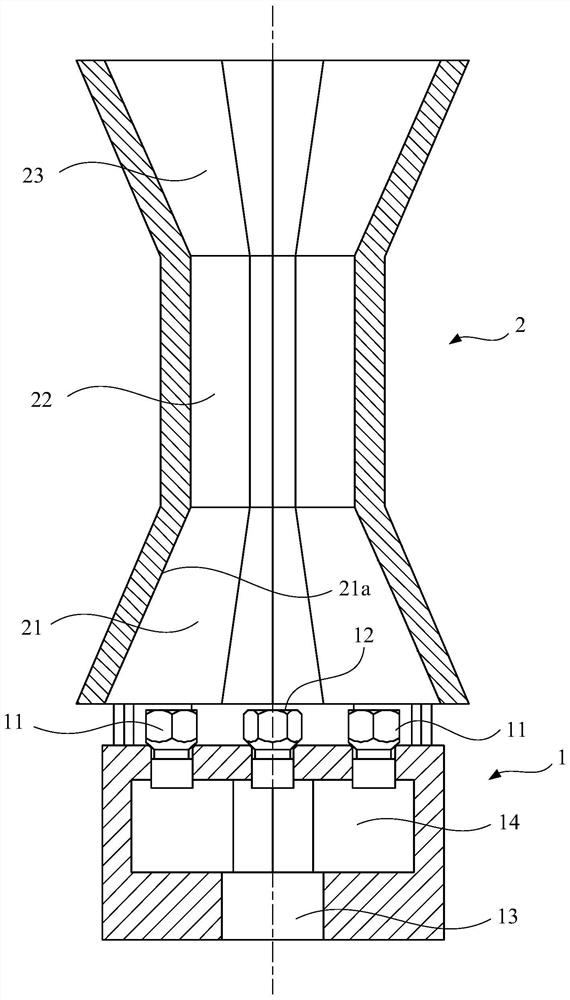
[0043] Such as figure 1 and figure 2 As shown, the present invention provides a cooker ejector, which includes a nozzle 1 and an ejector pipe 2 sequentially arranged along the airflow direction A. Wherein, the injection pipe 2 can be divided into three parts according to the change of the cross section along the gas flow direction, the constriction section 21, the horizontal section 22 and the expansion section 23, while the nozzle 1 includes a plurality of first outlets 11, and these first outlets 11 are Set toward the inlet direction of the constricted section 21, and these first outlets 11 are sequentially arranged circumferentially along the lumen edge 21a of the constricted section 21, so as to surround the lumen of the constricted section 21 (see for details figure 2 ). Through this structural arrangement, the gas ejected from the nozzle 1 from the first outlet 11 can directly act on the inner wall of the constricted section 21, which improves the air flow velocity o...
Embodiment 2
[0053] This embodiment provides a cooker ejector, the structure of which is substantially the same as that provided in Embodiment 1. The difference is that, in this embodiment, the injection tube 2 only includes the constricted section 21 and the horizontal section 22 , but does not include the expanded section 23 . Such as Figure 4 As shown, the end of the horizontal section 22 along the airflow direction A is closed, and a number of openings are provided on the side wall of the horizontal section 22, so that the mixed gas in the injection pipe 2 can communicate with the external stove fire cover. Wherein, these openings are arranged on the side wall surface of the horizontal section 22 around along the inner cavity section of the horizontal section 22 .
[0054] Since the horizontal section 22 in the present embodiment is also a polygonal structure, there is a corresponding relationship between the apertures of these holes and the straight-line distance between the holes a...
PUM
 Abstract
Description
Claims
Application Information
 - R&D Engineer
- R&D Manager
- IP Professional
- Industry Leading Data Capabilities
- Powerful AI technology
- Patent DNA Extraction
Browse by: Latest US Patents, China's latest patents, Technical Efficacy Thesaurus, Application Domain, Technology Topic, Popular Technical Reports.
© 2024 PatSnap. All rights reserved.Legal|Privacy policy|Modern Slavery Act Transparency Statement|Sitemap|About US| Contact US: help@patsnap.com