
Novel lock body

A lock body, a new type of technology, applied in building locks, door/window accessories, handle connections, etc., can solve problems such as increased cost, complex structure and maintenance, and achieve the effect of reducing overall cost, simple structure, and convenient linkage control.

Pending Publication Date: 2019-09-10
辛柏机械技术(太仓)有限公司
View PDF0 Cites 0 Cited by
  • Summary
  • Abstract
  • Description
  • Claims
  • Application Information

AI Technical Summary

Problems solved by technology

[0003] The control of this kind of lock is unilateral control. If you need to control double-sided doors, you need two locks, which greatly increases the cost, and the structure will become complicated and not suitable for subsequent maintenance and replacement.

Method used


Image

  • Novel lock body
  • Novel lock body
  • Novel lock body

Examples


Embodiment Construction

[0027] The present invention will be further described below in conjunction with the accompanying drawings and specific embodiments.

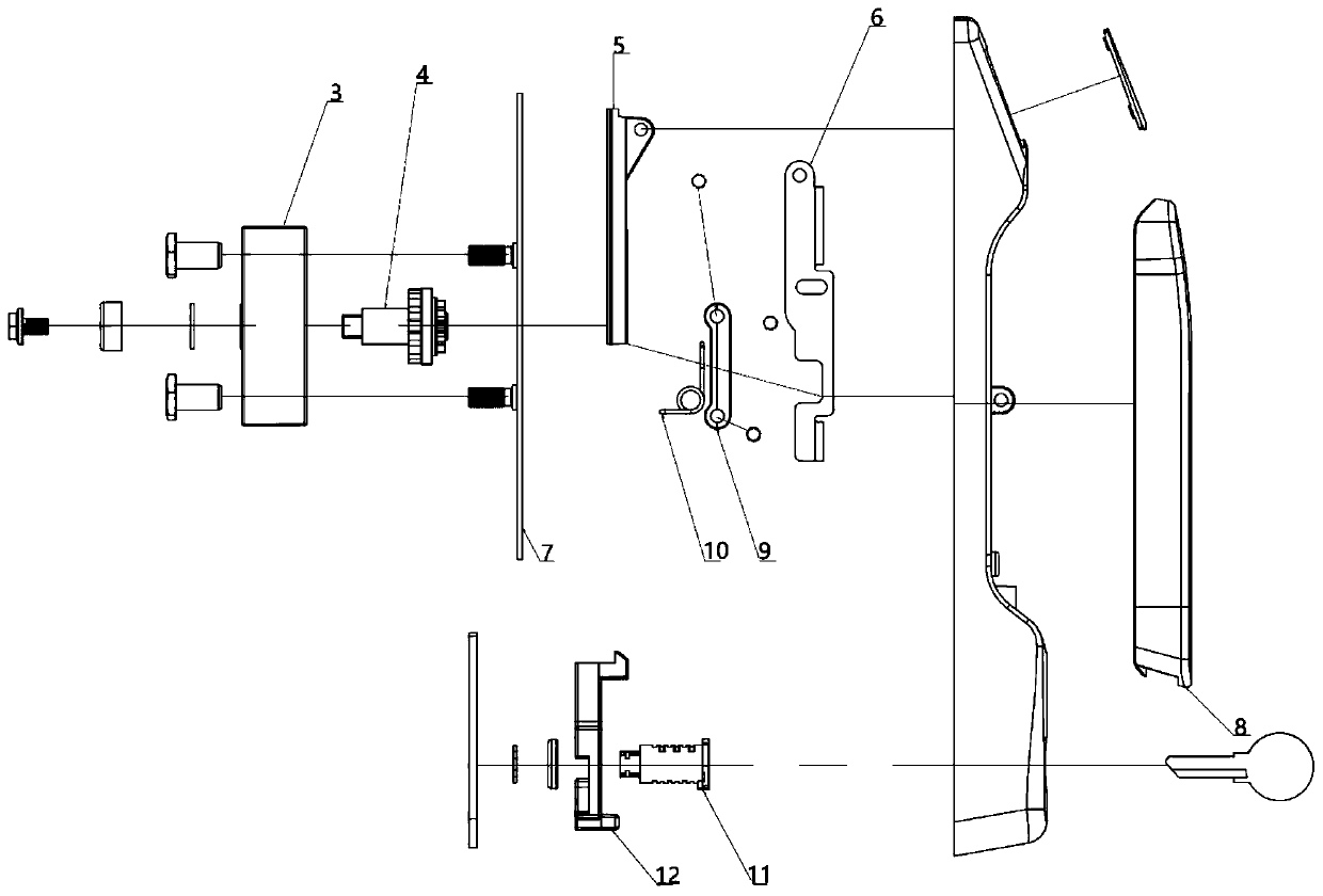
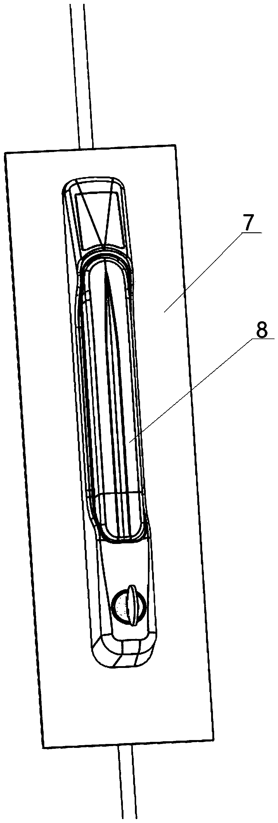
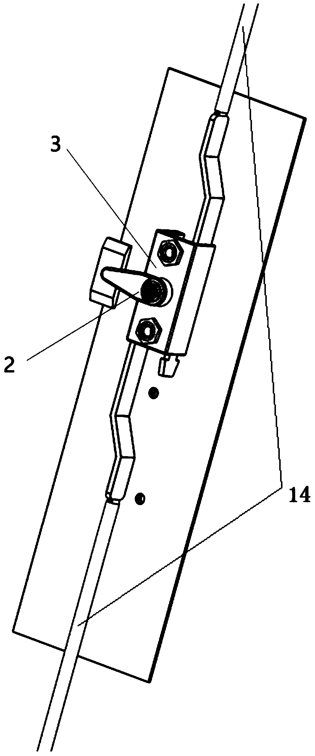
[0028] As shown in the figure, a new lock body includes a connecting structure 1, a handle 8, a lock cylinder structure 2 and a sliding plate 5; the sliding plate 5 is linked with the handle 8 through the connecting structure 1; the lock cylinder gear 4 of the lock cylinder structure 2 The side is in contact with the sliding plate 5, and the side of the sliding plate 5 close to the lock cylinder structure 2 is provided with a spur rack 13, which cooperates with the lock cylinder gear 4. The movement of the handle 8 drives the sliding plate 5 to move, thereby driving the rotation of the lock cylinder structure 2 to lock or open the corresponding electric cabinet door. The lock cylinder structure 2 can be connected with two lock rods 14, so as to control two interlocking door lock devices in different directions on the electric cabinet door, so a...


PUM


Abstract

The invention discloses a novel lock body which comprises a connecting structure, a handle, a lock cylinder structure and a sliding plate. The sliding plate and the handle are linked through the connecting structure. One side of a lock cylinder gear of the lock cylinder structure is in contact with the sliding plate. A straight rack is arranged on the side, close to the lock cylinder structure, ofthe sliding plate and cooperates with the lock cylinder gear. The novel lock body is simple in structure and can achieve dual-side control.

Description

technical field [0001] The invention relates to the field of lock bodies, more specifically, it relates to a novel lock body. Background technique [0002] The power distribution cabinet is a special cabinet for placing control components, which is mainly composed of a frame and a cabinet door. A lock for locking the cabinet door is provided between the cabinet door and the frame body. This type of lock is mainly composed of a housing, a lock cylinder assembly arranged on the housing, and a handle linked with the lock cylinder assembly. The handle is linked with the lock cylinder assembly through a rotating shaft. There is a fastening piece that promotes the fastening of the handle and the shell. When the lock needs to be unlocked, the handle is placed in the placement frame, and the other end of the handle relative to the end linked with the rotating shaft is fastened with the housing through the buckle; when it is necessary to unlock, the buckle is released from the hand...

Claims


Application Information

Patent Timeline
Patent Type & Authority Applications(China)
IPC IPC(8): E05B15/00E05B15/10E05B63/14E05B3/00E05B65/02E05B65/52
CPCE05B15/00E05B15/10E05B63/146E05B3/00E05B65/02
Inventor 张才德蒋海班宝林许艳梅
Owner 辛柏机械技术(太仓)有限公司
Learn More