
Coating device for striking surface layers of matches

A coating device and surface layer technology, which is applied in the field of coating device for match fire surface layer, can solve problems such as deviation of coating parts, poor coating quality, waste of phosphorous slurry, etc., and achieve reduction of consumption and waste, speed Fast, accurate effect on the coating site

Inactive Publication Date: 2019-09-10
NANJING LISHUI HIGH-TECH VENTURE CAPITAL MANAGEMENT CO LTD
View PDF4 Cites 7 Cited by
  • Summary
  • Abstract
  • Description
  • Claims
  • Application Information

AI Technical Summary

Problems solved by technology

[0002] The production of the fire-wiping surface layer in the matchbox manufacturing process is to coat the side of the matchbox with phosphorous slurry, which can spontaneously ignite through friction. In the traditional phosphorous slurry coating process, the two sides of the matchbox are simultaneously coated Coating, so that the limit device is set during the moving process of the matchbox, the coating pressure on both sides will make the matchbox move, resulting in the offset of the coating part, and the coating quality is poor. Secondly, when coating, the flow of phosphor slurry is controlled by Manual control, when the matchbox starts to be put in, the phosphor slurry placement cavity will be opened and circulated. At this time, the matchbox does not enter the coating part, resulting in waste of phosphor slurry

Method used


Image

  • Coating device for striking surface layers of matches
  • Coating device for striking surface layers of matches
  • Coating device for striking surface layers of matches

Examples


Embodiment Construction

[0020] Combine below Figure 1-Figure 6 The present invention is described in detail, and for convenience of description, the orientations mentioned below are now stipulated as follows: figure 1 The up, down, left, right, front and back directions of the projection relationship itself are the same.

[0021] The present invention relates to a kind of coating device of the fire rubbing surface layer of matches, mainly used for the work of coating the fire rubbing layer of the matchbox shell, the present invention will be further described below in conjunction with accompanying drawing of the present invention:

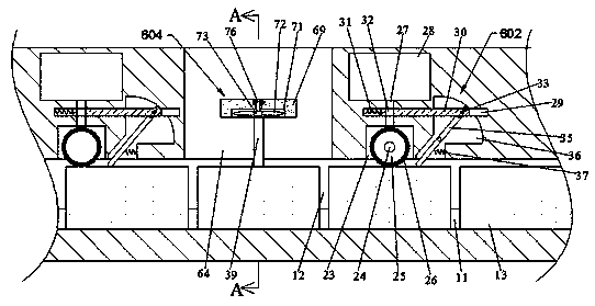
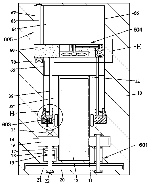
[0022]A coating device for a match wiping surface layer according to the present invention includes a body 10, a delivery chamber 11 is arranged in the body 10, a matchbox 13 is placed in the delivery cavity 11, and the matchbox 13 is to be The coated end face is placed in an up-down direction. Eight sets of conveying devices 601 are arranged outside the conveying chamb...


PUM


Abstract

The invention discloses a coating device for the striking surface layers of matches. The coating device comprises a device body, wherein a transport cavity is formed in the device body, a matchbox isarranged in the transport cavity, and a to-be-coated end surface of the matchbox is arranged vertically; eight sets of conveying devices are arranged on the outer side of the conveying cavity, the conveying devices are evenly disposed horizontally from right to left along the conveying cavity, and the conveying devices are connected through power; and the conveying devices work so as to drive thematchbox to move leftwards. Phosphor slurry is coated on both side surfaces of the matchbox through the coating device, and after one side is coated, the coated surface is dried through an air dryingdevice; and the other surface of the matchbox is turned upwards through a flipping device, the coating work of the next step is performed, and the process has automatic operation, a high speed and high efficiency.

Description

technical field [0001] The invention relates to the technical field of matchbox manufacture, in particular to a coating device for a match rubbing surface layer. Background technique [0002] In the production of the fire-wiping surface layer in the matchbox manufacturing process, the phosphorus slurry is applied to the side of the matchbox, and the phosphorus slurry can spontaneously ignite through friction. In the traditional phosphorus slurry coating process, the two sides of the matchbox are simultaneously coated Coating, so that the limit device is set during the movement of the matchbox, the coating pressure on both sides will make the matchbox move, resulting in the offset of the coating part, and the coating quality is poor. Secondly, when coating, the circulation of the phosphor slurry is controlled by Manual control, when the matchbox starts to be put in, the phosphor slurry placement chamber is opened and circulated. At this time, the matchbox does not enter the c...

Claims


Application Information

Patent Timeline
IPC IPC(8): C06F1/20
CPCC06F1/20
Inventor 刘纯
Owner NANJING LISHUI HIGH-TECH VENTURE CAPITAL MANAGEMENT CO LTD
Learn More