Non-contact motor stator winding dip equipment capable of eliminating liquid dropping phenomenon

A non-contact, motor stator technology, applied in the direction of electric components, manufacturing motor generators, electrical components, etc., can solve the problems of uneven amount of paint hanging, cannot be carried out at the same time, low work efficiency, etc., and shorten the paint dripping process. Effect

Inactive Publication Date: 2019-09-06
丁继来
View PDF0 Cites 0 Cited by
  • Summary
  • Abstract
  • Description
  • Claims
  • Application Information

AI Technical Summary

Problems solved by technology

[0003] Most of the existing paint dipping fixtures are of the contact multi-claw type, and the claws are fixed on the inner and outer circumferential surfaces of the generator stator windings, which makes the operation complicated and the work efficiency is low; the contact area between the claws and the generator stator winding surface is large, resulting in paint hanging The quantity is not uniform, and the contact part cannot be dipped in paint, which affects the effect of dipping paint. In addition, the claw size adjustment range is limited, which cannot meet the positioning and fixing of the stator windings of generators with different sizes and specifications. It is known from the information that the stator windings need to be pre-dipped before dipping paint. In the existing equipment, it is necessary to finish the dipping and drying of the stator winding after dipping. The two cannot be carried out at the same time, which greatly reduces the work efficiency. Therefore, a non-contact motor stator winding dipping equipment that can eliminate the phenomenon of dripping came into being

Method used


Image

  • Non-contact motor stator winding dip equipment capable of eliminating liquid dropping phenomenon
  • Non-contact motor stator winding dip equipment capable of eliminating liquid dropping phenomenon
  • Non-contact motor stator winding dip equipment capable of eliminating liquid dropping phenomenon

Examples


Embodiment Construction

[0016] The following will clearly and completely describe the technical solutions in the embodiments of the present invention with reference to the accompanying drawings in the embodiments of the present invention. Obviously, the described embodiments are only some, not all, embodiments of the present invention. Based on the embodiments of the present invention, all other embodiments obtained by persons of ordinary skill in the art without making creative efforts belong to the protection scope of the present invention.

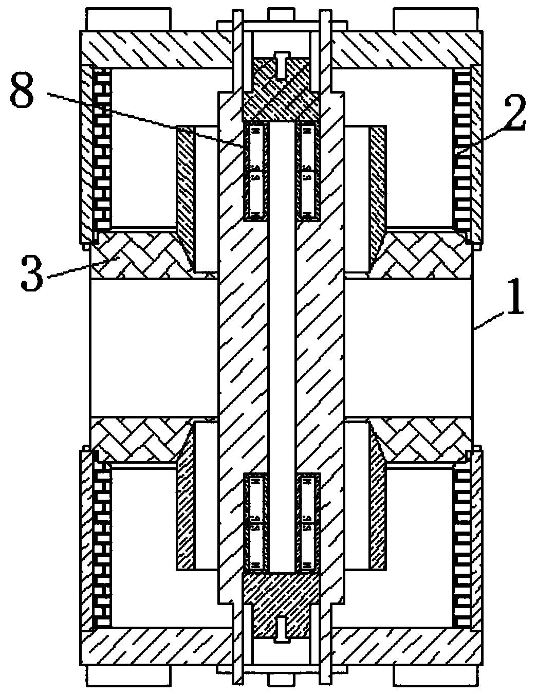
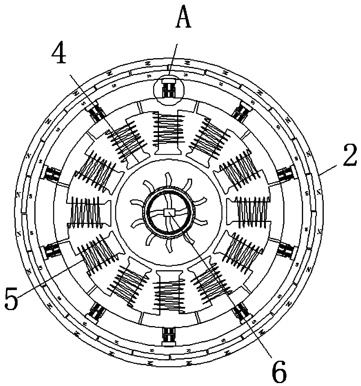
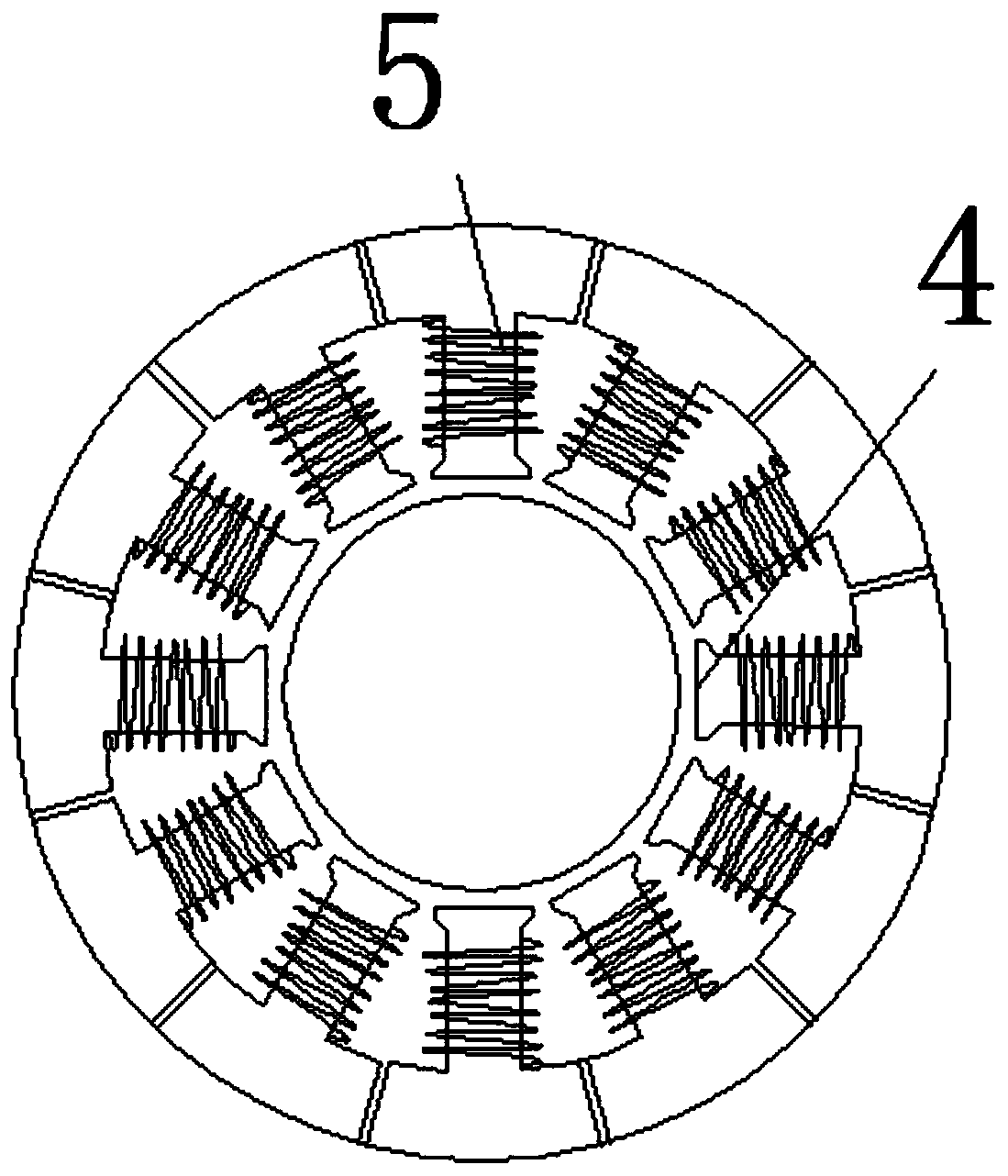
[0017] see Figure 1-5 , a non-contact motor stator winding impregnating equipment capable of eliminating dripping, a non-contact motor stator winding impregnating equipment capable of eliminating dripping, comprising a housing 1 and the inner side walls of the housing 1 Both are connected with electromagnet 2. The electromagnet 2 adopts a rotary electromagnet. When the rotary electromagnet works, it will generate a certain amount of heat. The inside of the el...


PUM


Abstract

The invention relates to the technical field of motor stator winding dipping. A non-contact motor stator winding dip equipment capable of eliminating a liquid dropping phenomenon comprises a shell, wherein electromagnets are movably connected with two side walls of the interior of the shell, a collection hole is fixedly connected with the interiors of the electromagnets by an adjustment mechanism,a heating wire is wound around a surface of the collection hole, a drying mechanism is arranged at one end, far away from the adjustment mechanism, of the collection hole, the drying mechanism comprises an air spraying hole, a magnet is fixedly arranged at one end, far away from the collection hole, of the air spraying hole, a drying passage is fixedly connected with one side, far away the air spraying hole, of the magnet, a dryer is fixedly arranged at one end, far away from the magnet, of the drying passage, hot air is sprayed out through the air spraying hole, a stator winding rotates under airflow influence, remaining insulation liquid on the surface of the stator winding can be dumped out during the rotation process, so that the dipping process can be reduced, the drying effect is achieved, and the dumped insulation liquid is collected by the collection hole so as to prevent waste.

Description

technical field [0001] The invention relates to the technical field of varnish dipping for motor stator windings, in particular to a non-contact motor stator winding varnish dipping device capable of eliminating dripping. Background technique [0002] The stator winding of the engine is the core component of the generator. The stator winding of the generator needs to be dipped in varnish during the production process. The varnish insulation treatment is an important means to ensure the life of the generator. The dipping treatment of generator stator windings requires dipping jigs to fix the generator stator windings, so as to improve the dipping efficiency and dipping quality. [0003] Most of the existing paint dipping fixtures are of the contact multi-claw type, and the claws are fixed on the inner and outer circumferential surfaces of the generator stator winding, which makes the operation complicated and the work efficiency is low; the contact area between the claws and ...

Claims


Application Information

Patent Timeline
Patent Type & Authority Applications(China)
IPC IPC(8): H02K15/12
CPCH02K15/12
Inventor 丁继来
Owner 丁继来
Why Eureka
Try Eureka